
![]()
Measurements:
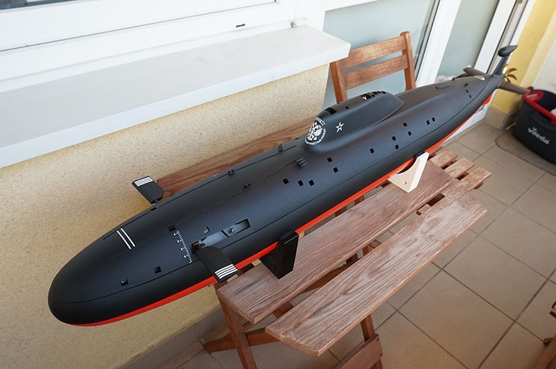
- Scale: 1/90
- Length: 1225 mm
- Displacement (surface): 10.5 kg, (submerged): 11.5 kg
- type: Static diver (Engel T-max)
Build:
Build Start: 05 Feb 2016.
Build End: 1 June 2017.
Maiden Cruise: 10.09.2018 Bratislava – Sub Regatta 2018
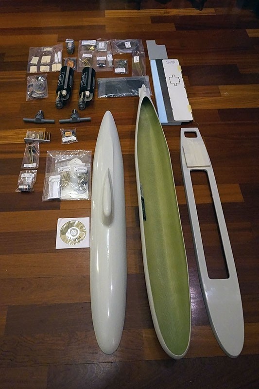
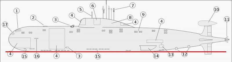
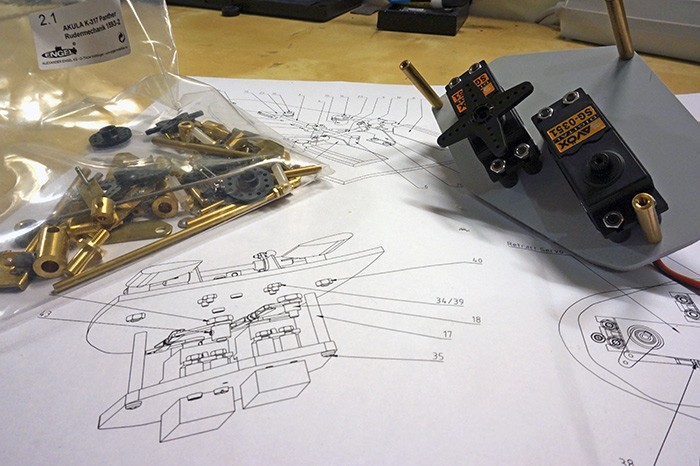
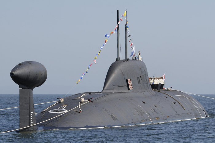
One of the Engels kits with the details on the hull. Building threads of those are not that common actually, cause of two reasons mostly. The kits price and the need of a well equipped workplace. Personally, before constructing or even choosing a model submarine kit, I treat threads like this – from other model makers like gold mines of various informations. My kit is the version with the T-max microprocessor ballast tanks control, with retractable bow planes and retractable periscopes. The kit was a Christmas 2015 gift from the Fleets Admiral – my lovely Wife.
So called “box contents” photographed the right. Of course missing all the servos, ESCs, RX, wires and the resin.
Funny fact:
The codename “Akula” was given by NATO for the Scuka class submarines.
The Russians by the codename “Akula” describe a completely different submarine type – their 200 meter long “Typhoon” (“Typhoon” is the NATOs codename).
…but…
One of the many Scuka-B submarines was given a name: “Akula”…
Simple to understand, right? 😉
Akula (Акула) means “shark” in Russian.
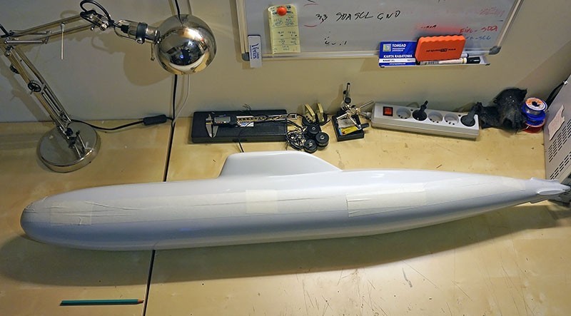
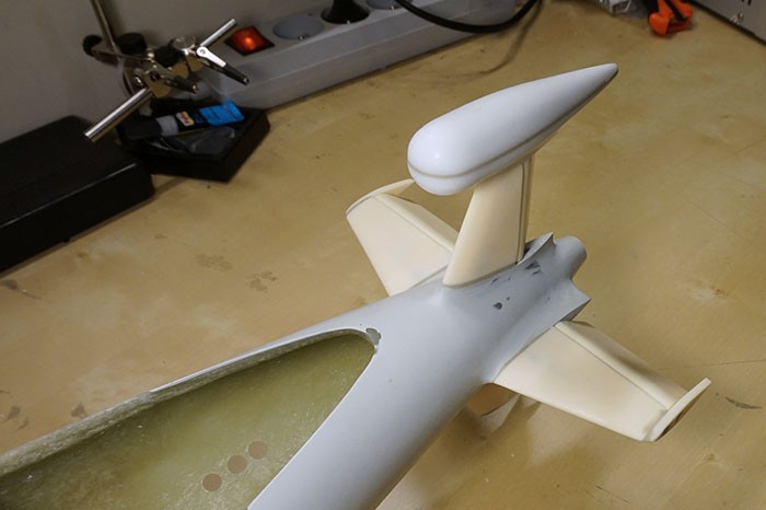
At the very start – you need a lot of strength as both parts of the hull require quite a force to fit them together. Still the fit is much better then in my Engel Typhoon.
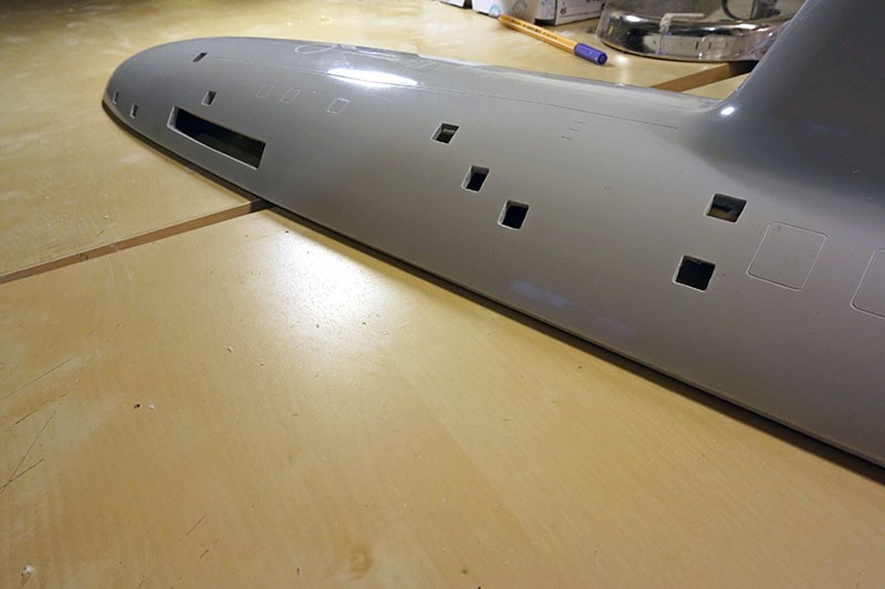
Pencil for scale.
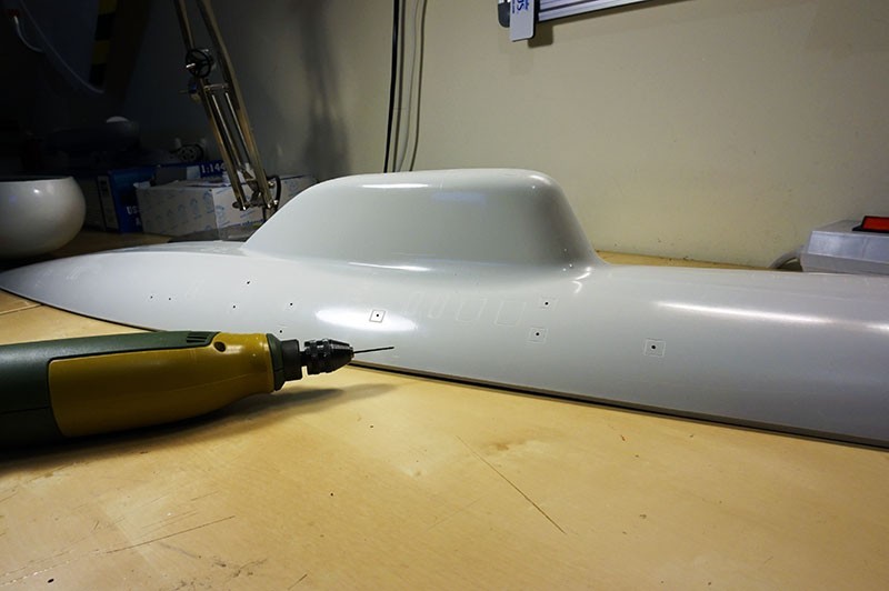
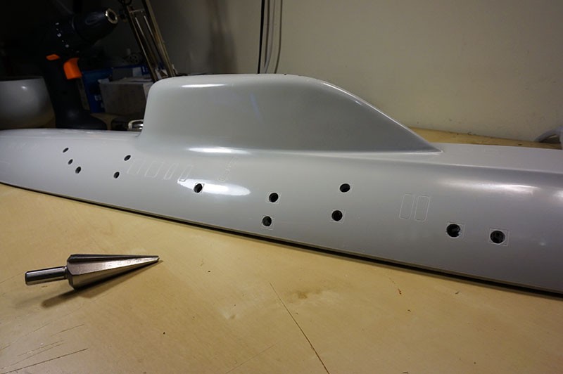
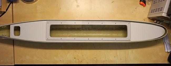
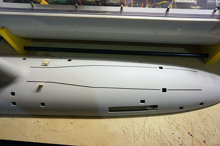
Cutting the flooding vents – upper hull.
Cutting the vents in the upper half was the first step in this long walk of creating my own Akula. First I’ve drilled small holes with a 1.5mm diameter drill (about 0.59 inch). Then each hole was widened with a reamer (for metal works). In my opinion a sharp reamer is much more safer then a drill. Especially as the model has a glossy covering. Of course, if something goes wrong you can always repair the damage with some putty so no worries, but it’s always better to be on the safer side. When the holes were in the right size finally, I’ve slowly filed them into the desired – mostly squared shapes. Personally I like this part of the model making, even with all the lung irritating dust.
 |  |  |
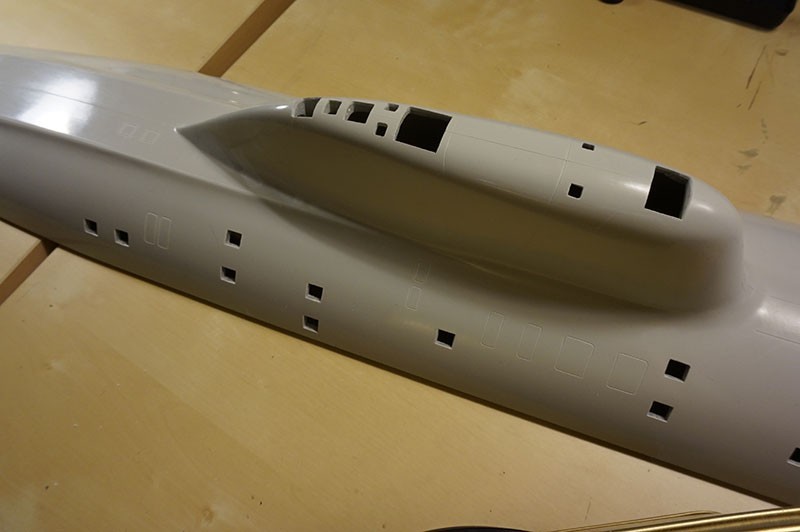
The openings in the sail were the last to make. These are very important cause of two reasons: Firstly – these are the holes for the retracting periscopes and antennas. Secondly – they’re venting the wet hull during the dive. I did not expect that it will be the hardest part of all the file work. Laminate on the sail joints is extremely thick and hard. The sail all alone took me as much time as both sides of the hull all together… I put this in my build thread to warn everyone who plan to buy this kit. GOOD quality files are essential, and it is necessary to stock up with a square and rectangular one – ideally two of each.
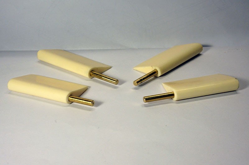
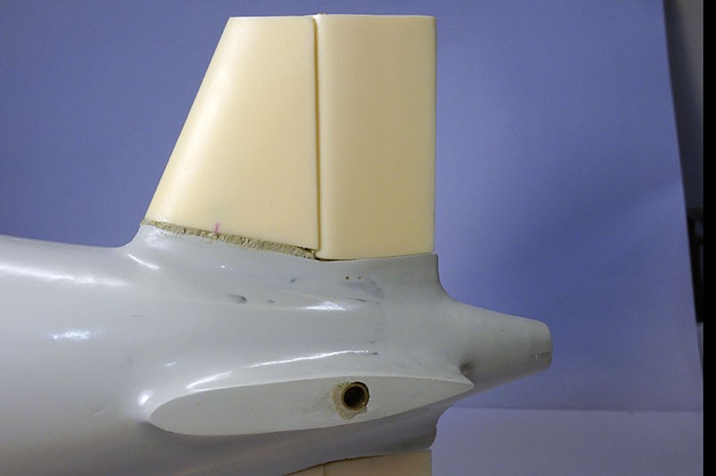
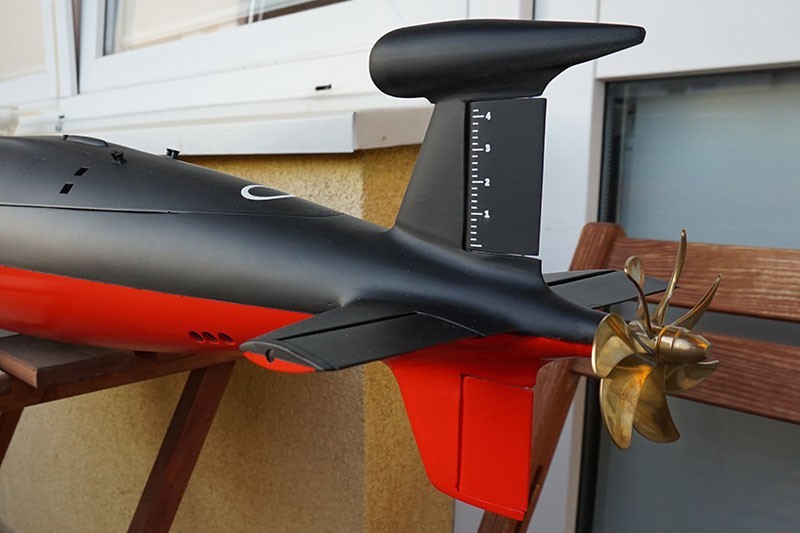
Stern diving planes and rudders.
First you need drill the holes in all the rudders and diving planes for their 4mm shafts. It’s a bit dangerous job as, they’re quite thin – 7mm, which means you’ll be leaving only 1.5mm of the original resin at each side. You only have one shot for that and If you don’t do it upright you might end in destroying a rudder completely. Take your time, use fresh drills. Bench drill is a must, low rpm. After that you’ll need to place the axes in the holes. I add some glue to make sure they’ll stay there forever.
The stern of the hull has been drilled with a 5mm diameter drill to place the brass “bearings” for the rudders and planes axes. Excessive space filled with resin, everything sanded down with 800 grit paper.
 | 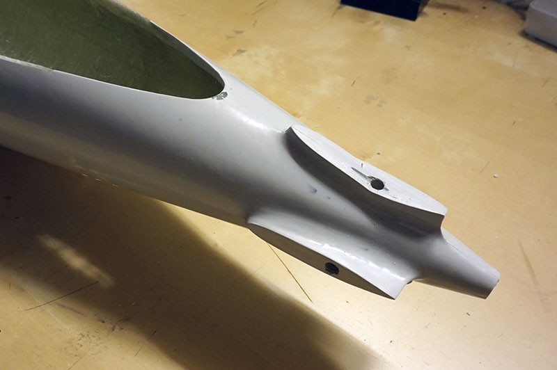 | 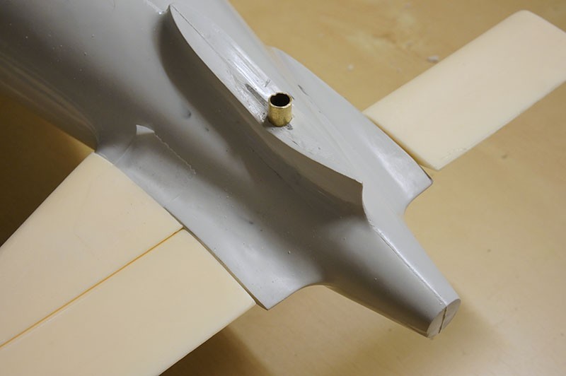 |  |
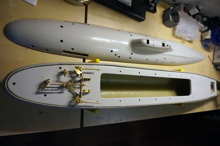
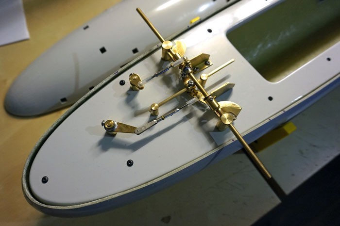
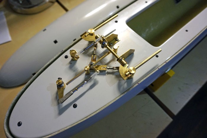
I’ve managed to do everything perpendicularly. Next step was to fit and connect everything inside. Not much space there and in addition you’ll need to run the damn shaft right in the middle!
Before putting everything all together, I’ve noticed a slight design problem which has been copied from the original vessel. Okay, so what the guys from the Malakhit Marine Engineering Bureau f*cked up and Engel copied it?
The lower rudder is to high in my opinion. In contrast to the real vessels, the submarine models park on ground much more often. We also run our models in artificial pounds with rock bottoms or in the concrete pools. It’s really not to hard to dive a bit to deep and “scratch the belly” against the bottom. After all we control our vessels from the shore by looking at them, sailors control theirs by reading and analysing lots of various sensor/map data. It’s not that hard to find some information in the Internet from people claiming to be working in shipyards with those Russian boats and also complaining about often problems with the lower rudder being damaged. A rudder sticking outside of the vessels contour is much more subjected for damage and even breaking off. It’s also worth to mention, that when you place the model on any hard surface – for example your workbench, you’ll be putting a lot of weight on that poor rudder too.
As the main rule in underwater RC says “If there’s an element in your model which you suspect that may fail – it will fail for sure and most likely while submerged.” The decision was was made, that I will modify the rudder!
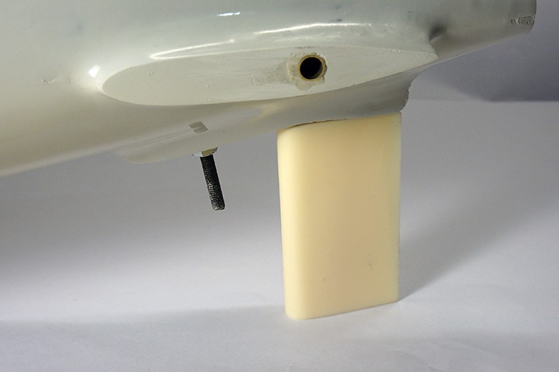
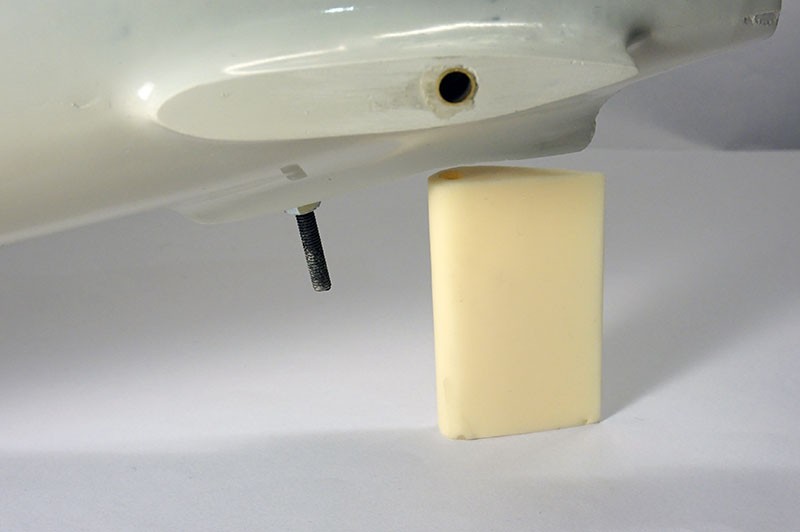
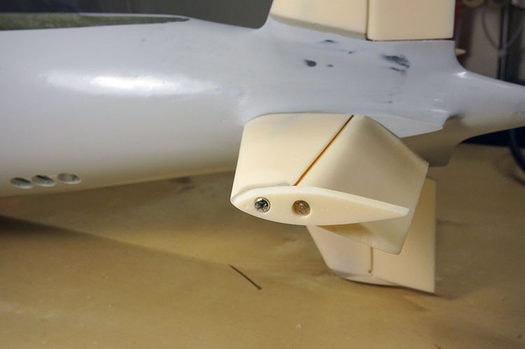
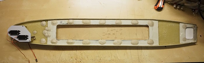
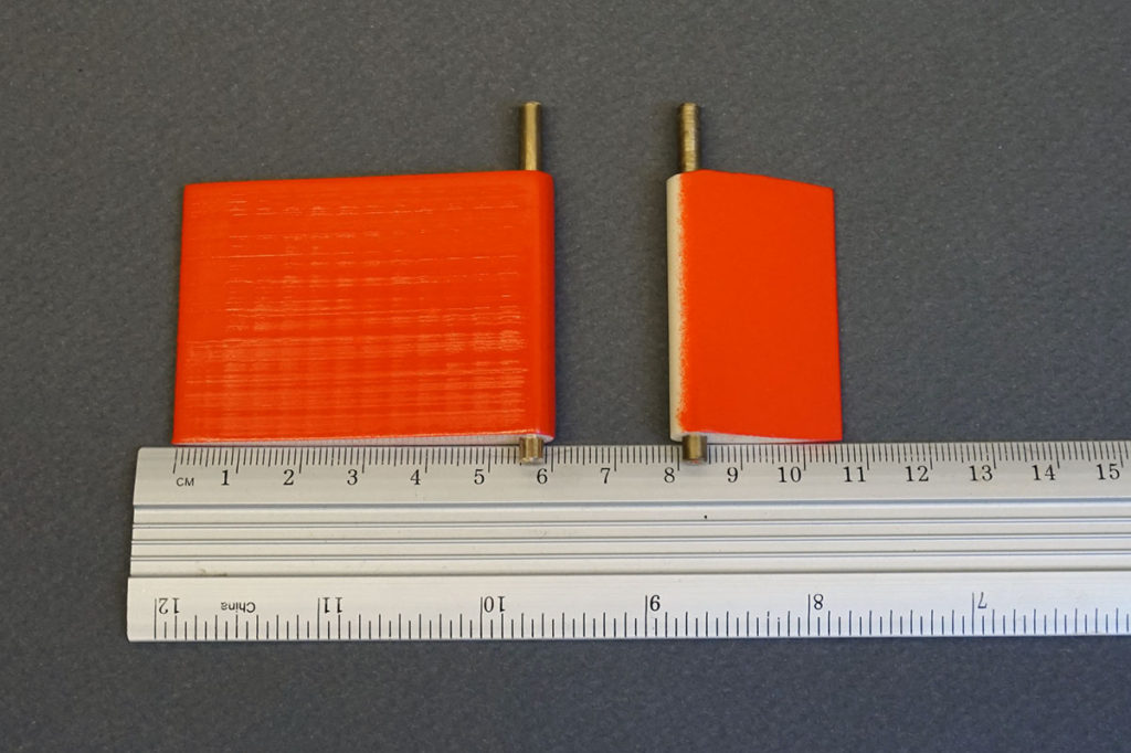
Left photo – before modification, model rests partially on the rudder. The Akulas final weight will be around 11kg! On the right: modified rudder*
*After first trials I know now, that I would change the rudder shape completely and I did that modification on 28.05.2019..
Filling the gaps and sanding to make the surfaces nice and smooth:
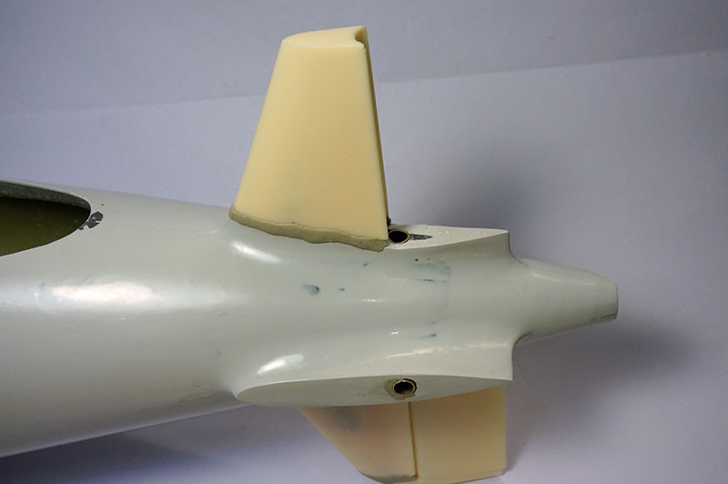 |  | 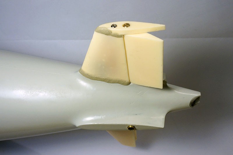 |  |
Some of the gaps required almost 3mm of resin. At that point, it wasn’t filling the gaps – it was rather creating new bases for the fins.
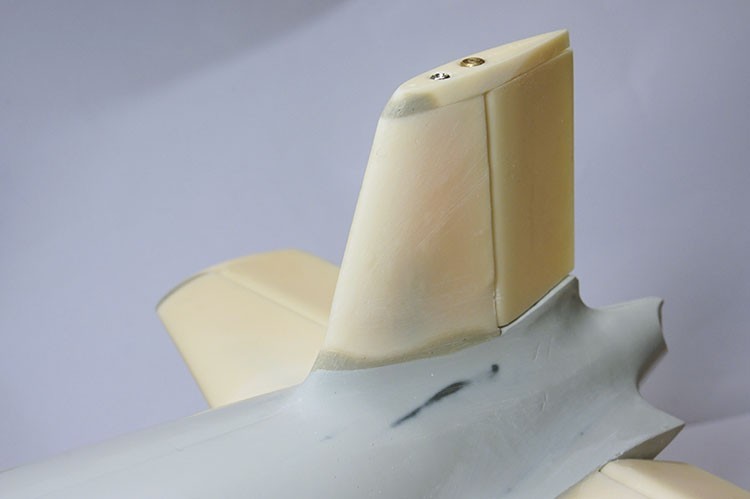
Finally everything was fitted and sanded down perfectly. The characteristic housing of the towed sonar array was filled with putty.
“Middle Deck”
This part of the build includes lot’s of hole drilling with various diameter drills for different things. Engel supplies their kits with a heavy, non transparent, metal cover.
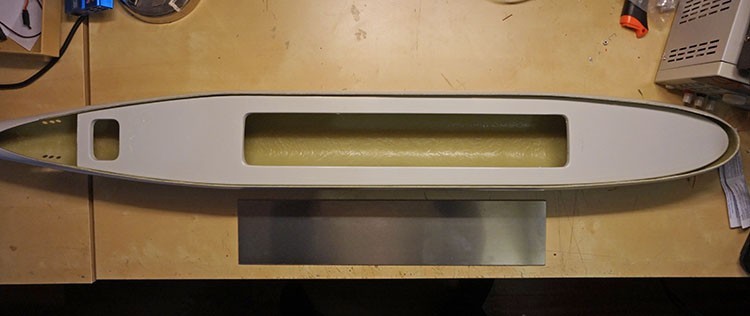
The metal cover in my opinion is something far away from a perfect solution. It blocks radio waves and it’s very heavy, raising the CG of the boat unnecessarily.
The cover is also the mounting base for the retract mechanism of the periscopes and masts. Engel supplies a detailed drawings how you should drill the cover with various diameters from 2mm to 4,2mm for periscopes and 4.5mm, 5mm, 6mm for few other things. You really need LOTS of sharp drills to finish this kit.
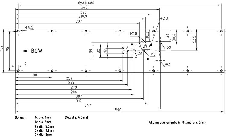
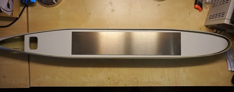
So before all that precise drilling, I made a decision about replacing the aluminium lid with a transparent – polycarbonate plate. I’ve done the same mod with my other Engel kit – the Typhoon. It allows an easier inspection for leaks and looks much better. Does not block the radio waves like aluminium too.
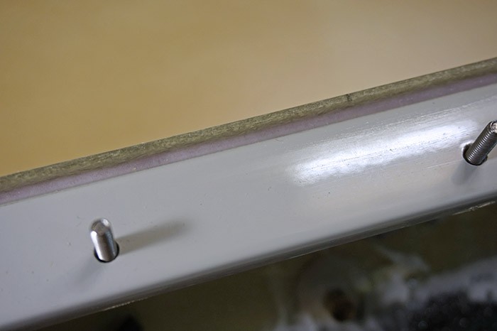
On the right you can see the process of the d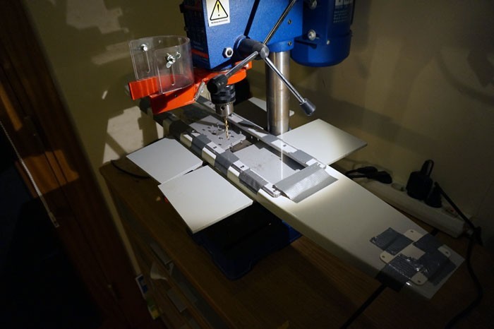 rilling the holes in the middle deck with the new transparent lid at the same time. If you want to have a perfect aliment of the screws and keep the thing watertight, it’s best to drill both things at once. I used the duct the to secure both of them tightly together and then drilled the holes in both parts at once. I would recommend the use of highest quality drills (for metal) as possible cause the middle deck has been enforced with steel bars inside.
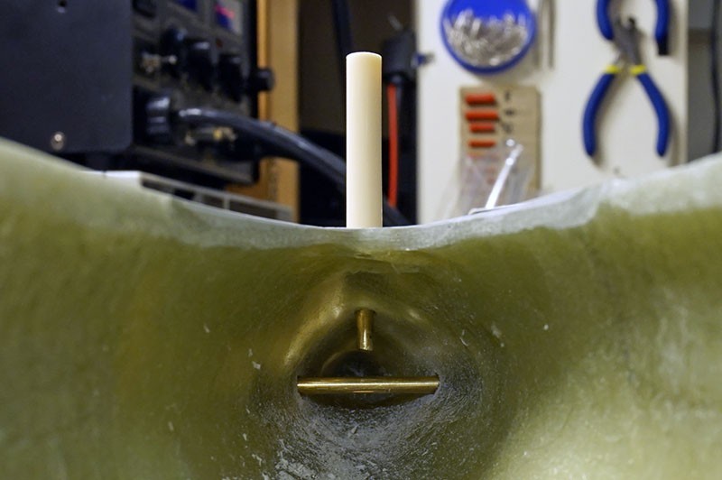
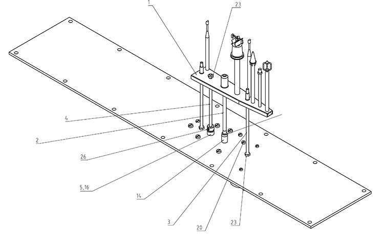
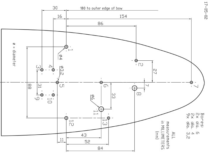
Bow diving planes:
Drilling the holes for the dive planes retract mechanism was even harder. Just look at that scheme. It’s a good idea to have a precise ruler and even calipers. Engels supplies the kit with a plastic drilling template, but personally I found the thing useless. In the end I’ve managed to drill everything in the correct measurements and symmetrically. Skills and luck…
Looking good! One of those “finally something happening here” photos:
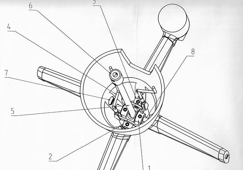
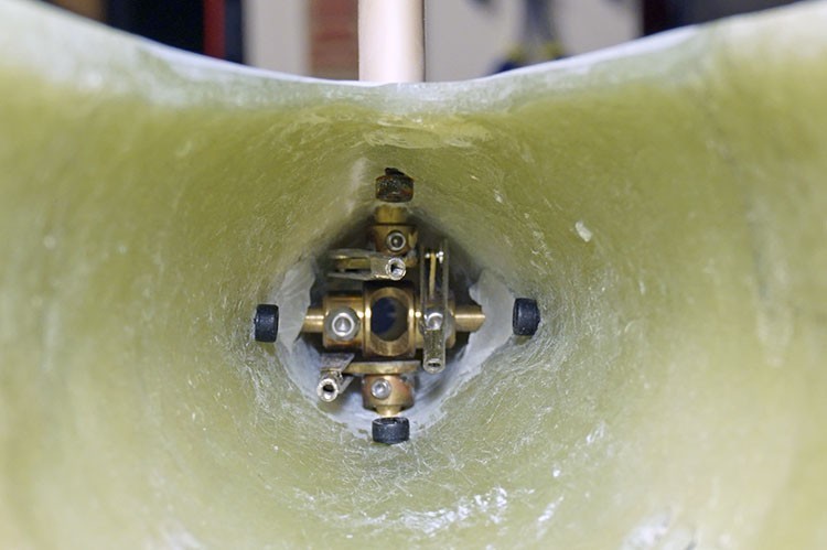
The fully assembled and soldered mechanism: Extracted on the left and retracted on the right.
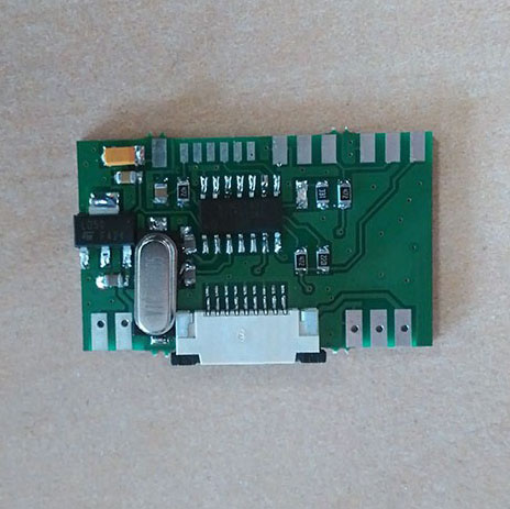
Retractable dive planes electronics:
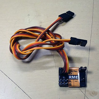 It’s a common knowledge, that Engel is still in the 90s with some of its solutions. But the supplied retract mechanism controller is simply to much!
Look at the photo. If you have some RC electronics knowledge you might suspect that it works like this – one servo cable for the dive plane servo, while the other you use to connect for retract servo, right? NO…
One of those servo plugs is for the dive planes operation, while the other is simply for setting up the endpoints of the retract servo. Yes… Endpoints… After setting those, you disconnect the second plug and just keep it loose in your hull. The controller needs a GND at one of the pins to begin extraction of the planes. If you want to retract the planes the GND needs to be disconnected from that pin (!). I know that many of the submarine model makers are 55+, but that’s just ancient! So you additionally need something which will ‘translate’ a PWM channel signal into “GND/ no GND”. To make this work Engel recommends using “duo switch” (or something like this), it which was produced by the LONG GONE Robbe. That’s seriously sad. It’s year 2018 – If your a submarine model builder it’s more then high time to use a TX with endpoints settings via the build in computer.
Of course it’s very simple to make a GND/no GND controller with a servo and some kind of switch, but how about some ambition? Well I’m ambitious, so I’ve decided to make my own dive planes controller based on the Arduino platform.
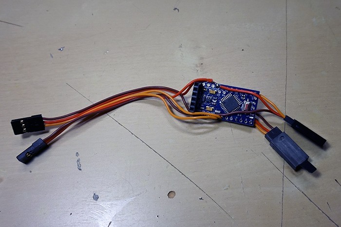 Soldering the wires is something even a child can do, the challenge was the program.
After two long evenings and few cups of coffee I’ve managed to make the thing working like I desired:
1. Extracts the dive planes in slow motion
2. Turns on the dive planes rotation servo only when the planes are extracted.
3. After getting the “retract” command, puts the dives planes rotation in neutral.
4. Waits a little.
5. Retracts the planes in slow motion.
 Driver functions
– 5V input directly from the receiver.
– two servo plugs for everything (no “duo switch” or other crap, only PWM straight from RX)
– slow motion of the retraction/extraction
– user selects the retract speed
– sets the dive planes into neutral after getting the PWM “retract” command
– locks the planes servo while retracted
– neutral position while extracted and neutral while extracted can be defined differently.
– Setting of the end points by a pot on the driver OR STRAIGHT from the TX.
They say that a movie clip is worth a thousand words, so enjoy (English subtitles soon!):
Preparations for glueing in the middle deck.
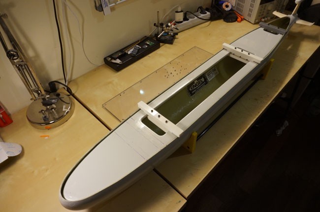
All the screws passing through the middle deck have been glued in, making sure the thing will be watertight. It’s the last time, when I’m able to look at my middle deck from this angle. It’s time to glue it together with the lower hull. I’ve checked everything like 10 times already.
 The middle deck needs to be glued in with resin to the lower hull. It’s a critical part of the build, as If you’ll glue it to high, you’ll get problems with upper hull alignment and the proper waterline. If you’ll glue it to low, you might not be able to move the piston tanks in…
The middle deck needs to be glued in 3mm below the upper edge of the lower hull. You can do it only once, there is no way to correct it.
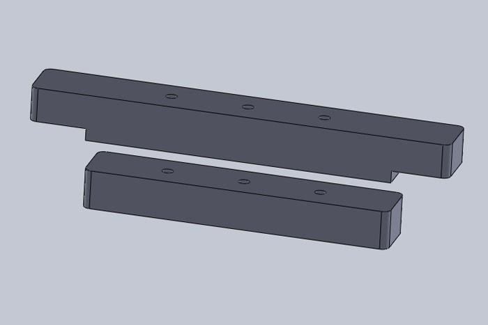
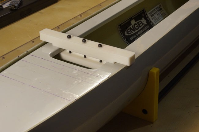
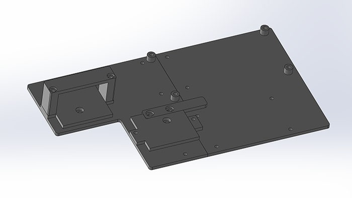
That’s why I’ve made myself an additional element – a tool which enables me to hang the middle deck exactly 3mm above any edge. The element is made out of two printed parts and three M3 screws.
As you can see it’s very easy to use it and it’s a great help! When glueing my middle deck, I was using 3 of those – all 3d printed.
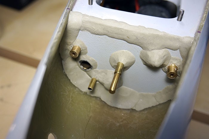
Glueing in the middle deck – working with resin:
Long story short – thanks to all those long and careful preparations, I’ve managed to do it not only correctly, but also nicely and clean looking. The resin was applied with a 2ml syringe. I’ve patiently waited for it to run in smoothly into the crevice, then applied again. Something like 12 hours of work spread over 4 days.
Photos of the details, excessive amount of resin has been wiped out before it dried.
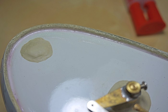
The hull with the middle deck is now hard as a rock!
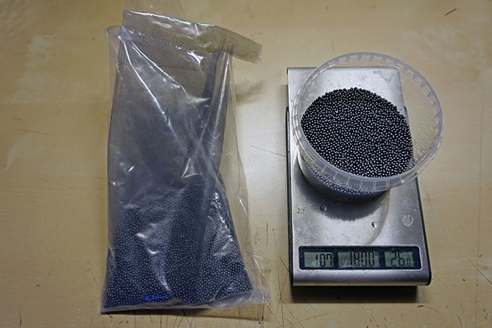
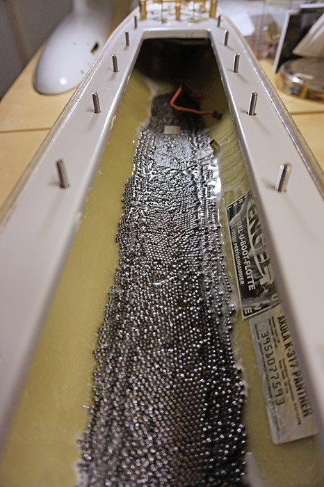 While working with the resin, I’ve also glued in the the lead ballast. Again, it’s very important to make it smooth and no taller then 8mm. I’ve used 1800 grams.
Nowadays, after the “sea” trials, I already know that was not enough, mostly because I’ve changed the aluminium lid to the polycarbonate one, which is much lighter.
Bulkhead – main motor section:
I’ve cut the bulkhead from the supplied piece of laminate. I had to make myself a paper template first. Then I’ve used my lucky fretsaw and was able to cut out a neat bulkhead. Way to much dust for a work at home…
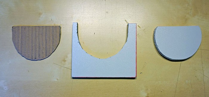
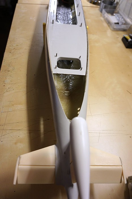 Photo on the left with the middle deck glued in, yet without the last bulkhead.
The cut out bulkhead needs various hole sizes – for the pushrods, main shaft, breather tube and the aft dive tank water inlet. It’s also the mounting place for the gearbox and the motor. It’s crucial to glue the bulkhead in perpendicularly to the middle deck – if not, you will have problems with the shaft alignment. In the earlier part of my build thread, you could see the assembly of the dive planes and rudders mechanism and that you don’t really have any margin for error – as if yo mount the shaft on a wrong height, angle or not coaxial it will not fit the tight space in the stern.
The bulkhead glued in, (with the motor fitted in too). Maybe it doesn’t look pretty to glue it in with “Poxilina” putty resin, but that stuff is just insane. I’m using it for something like 15 years already in all my boats and it never let me down.
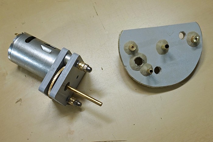
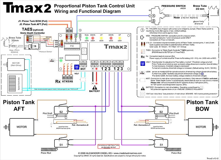
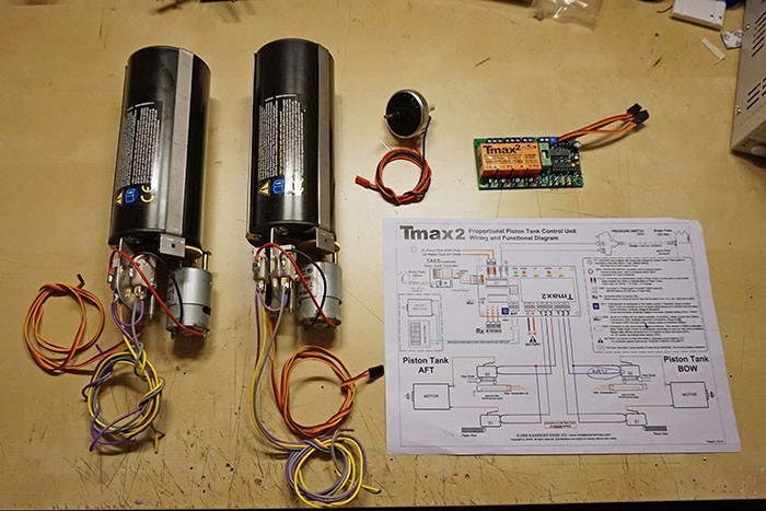
T-Max ballast system:
This particular Akula kit has been supplied with T-max II – it’s a type of Engel ballast system. It consists of a driver and two piston pressure tanks. There are several versions of the Engel dive systems and T-max is the most advanced one. Except normal operation of the tanks, it also allows for trimming the tanks at once or (almost) independently. After getting to know the system I personally think it’s not that hard to make the T-max driver yourself and if I’ll be getting myself into a scratch built – I’m planning to make my own driver based on Atmega or Attiny processors. Below is the T-max wiring diagram, much simpler then the older TAES type – like the one in my Typhoon.
 Both tanks with wires soldered – getting ready for the first test.
Testing the T-max II – movie clip (polish language, I’ll make subtitles someday):
Batteries and electronics compartment:
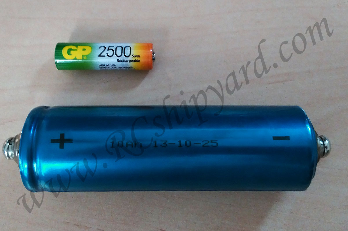
Plastic 3d printed parts are being used more and more often by us model makers. Personally, I use them mostly for simple details or for larger mechanical elements. In my Akula I’ve created an electronic and battery carrier from scratch. I’ve changed the type of batteries, because like I said earlier Engel is a nice company, but they have serious problem with still being in the 90s with their ways of model making – a recommended pack for the Akula consists out of 5 Ni-MH cells. Yes – Ni-MH… Still they could recommend using Ni-Cd, so I suppose it’s not THAT bad. Anyway, I thought that it’s time for an upgrade, so I’ve decided to power my Akula from two Li-Fe cells (3,2V each). They’ll make a nice juicy 6.4V 10 000 mAh battery pack. On the picture you can see a single cell with a GP AA size cell for scale.
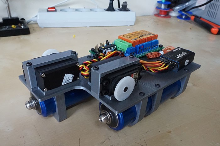
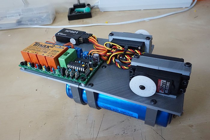
After some cad designing and 3d printing, I’ve came up with my own electronics carrier. T-MAX II driver, two servos, RX, two giant Li-Fe cells and 4 AA cells for the receiver – everything has it’s place. Yes, there will be a 4.8V pack too, as I don’t like BECs to much.
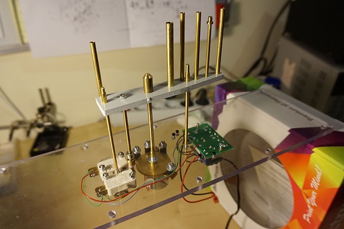
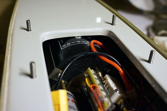
Periscopes and antennas retract mechanism.
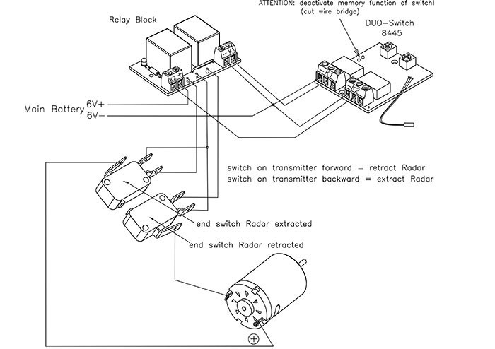 In my Typhoon, as my funds were really limited back then, I’ve created a scratch build periscope retract mechanism based on a scissor lift. How it looks and how it works you can see HERE. After the assembly of the original Engel mechanism for Akula I seriously regret asking ‘santa’ about it. I should have done the same mechanism myself as with the Typhoon. Of course the thing looks really good. It has a high quality mechanism, but still it’s way to heavy, to bulky and you need that damn Duo Switch AGAIN! Really?! How hard it would be to add a microcontroller for 2$ and integrate the PWM control in that damn thing?! About Engel replacing the bulky relays to mosfets we can only keep dreaming too!
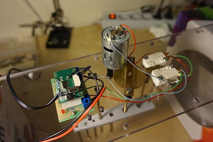
 So again, I had a problem of not having that DUO switch crap and had to thing of something. I was going to use an Arduino Pro Mini board, but sadly I had none at home at it was Saturday evening. Luckily I was able to find an unused control board for a multicopter drone camera. It had an ATTINY processor on board so it’s basically like Arduino. Actually it was something you would normally consider as electronic scrap, but it was still operational. I’ve removed some of the elements with my hotair station, flashed a new firmware, which talk an hour to write and it worked!
Mounting the mechanisms and the electronics into the hull:
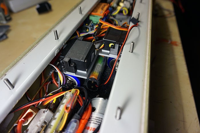 The 3d printed electronics carrier goes in tightly, but without bigger problems. It has been glued in with a small amount of resin – in case I would have to remove it. Between the two main Li-Fe cells, a 4.8V AA 2500Ni-MH pack for powering the RX has been placed. I try to avoid BECs – especially switched BECs as they greatly reduce the range of the 35 and 40 MHz receivers.
A bit earlier in my build thread, I’ve clearly noted that it’s very important to glue in the middle deck exactly 3mm below the hulls edge and that is also very important that the glued in lead ballast will be equal or less then 8mm in height. Now you’ll know why. Look high tightly the ballast tanks fit. You can barely slide a paper sheet between the hull and the tank.
About 10 years ago, while I was making my Typhoon I’ve read an almost tragic building thread on one of the forums. There was that guy (I think he may have been American), who didn’t put much care about those measurements and in the end he wasn’t able to finish his build. It’s one of the reasons why this kit has a rather shady reputation in the model makers society. Unfair in my opinion. I would just call this model difficult, or simply requiring accuracy.
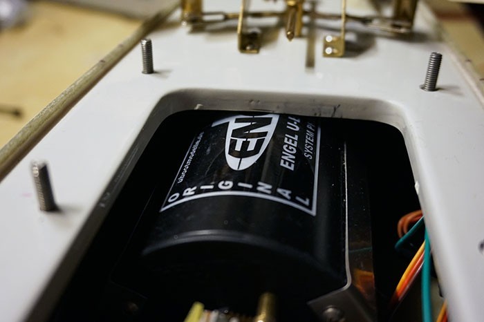
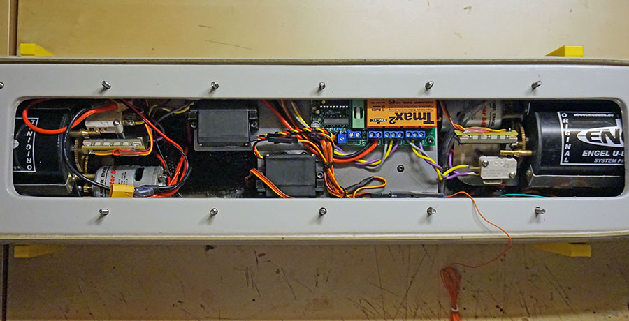
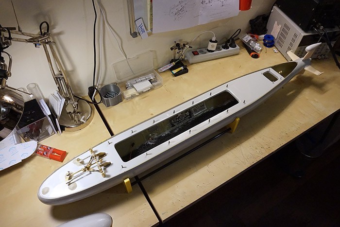
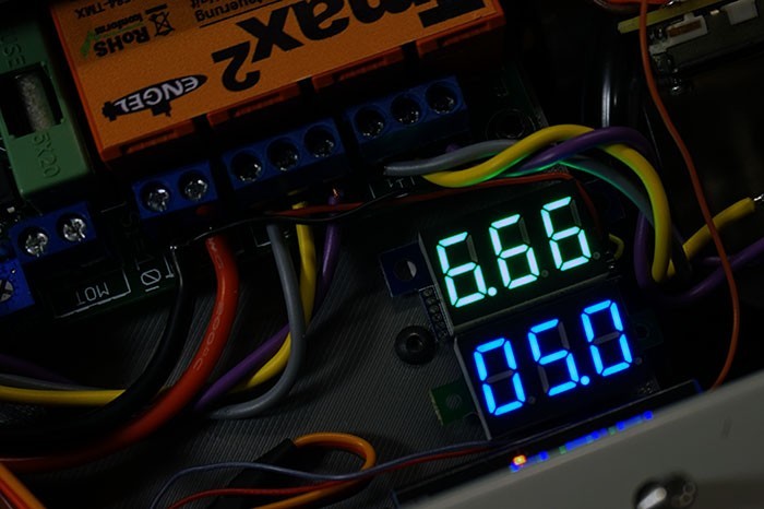
Finally the time came to fit the transparent lid and to check does it slide in smoothly on the screws after the oversized periscope retract mechanism has been mounted. It was ok. I’ve also added two voltage meters – one for the main battery and other for the Ni-MH RX pack.
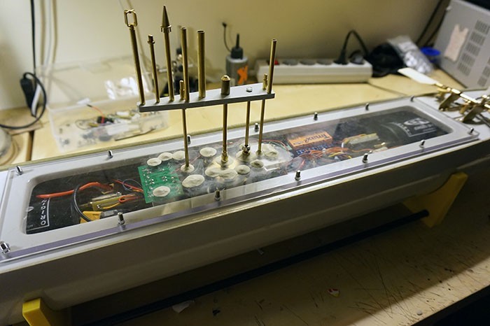
Testing the mechanisms working all together for the very first time:
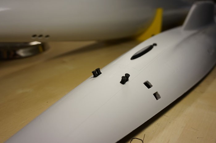
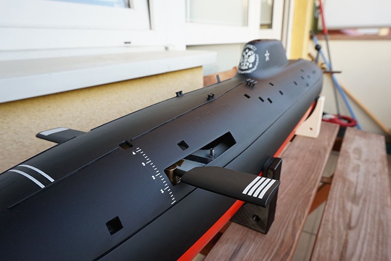
Hull details.
Akula doesn’t really have many details on the hull as it’s a submarine. I did some research and examined the photos which Engel also provides. I was sure that I’ll just need few more details
Photos helped a lot. There are lots of them in the web too. It’s a little sad that Engel doesn’t really supplies all the details – especially with the price of the kit and the low cost of making some extra resin elements. I’ve created the missing details with a help of a 3d printer of course.
At the stern, the missing elements were ballards and two ’embossments’ of an unknown function.
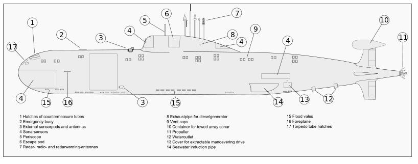
On the ‘blueprint’ you can clearly see that Akula has stern manoeuvring drives. I was planning to add those too, however in the end I have decided that, I’ll keep my in the box and see do I really need one.
Periscopes, radar and radio antennas details.
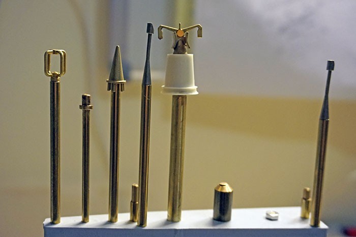
Engel supplies a very decent set of those for assembly:
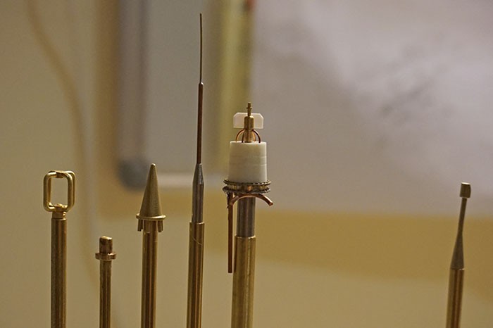 However… I thought I’ll use the different ones. With much more details:
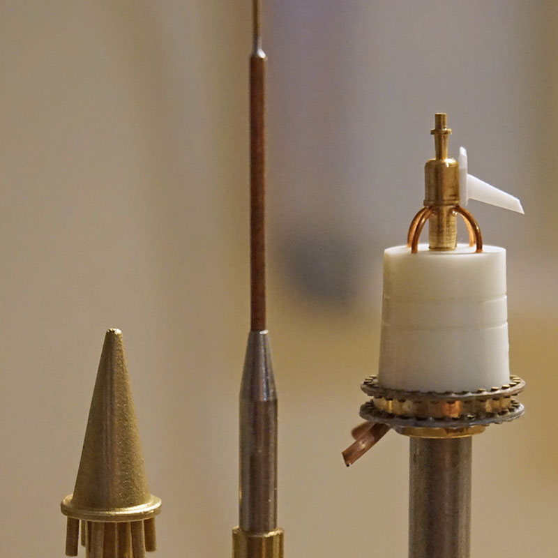 Close up of the details:
Painting:
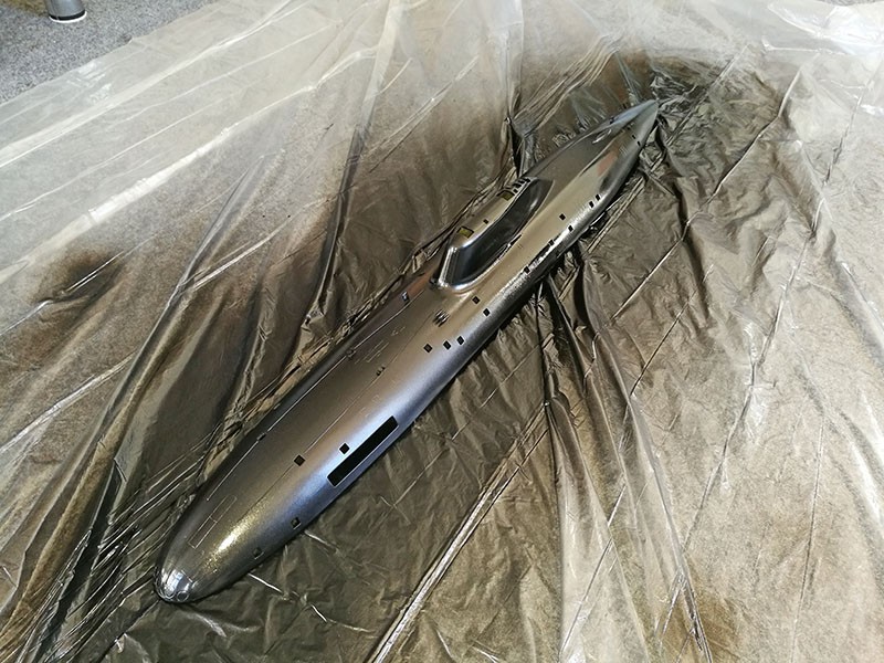
The first attempt of painting the hull was a real catastrophe. I bought some really low quality paint, even when it was quite expensive. The effect was terrible – half shiny black with lots of “orange skin” facture. I was very sad and and angry at the same time…
…however model making teaches you the art of patience.
When all the negative emotions were gone, I took the hull, removed all the details, bought lots of sandpaper and sanded off all the rubbish paint. After that, I got back with the paint I’ve always used – Chaos Black and I was finally happy with the result!
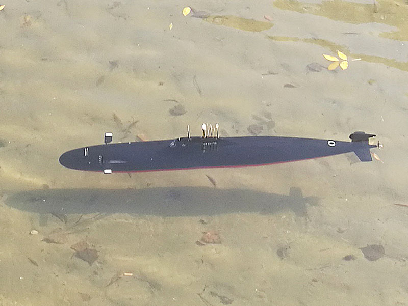
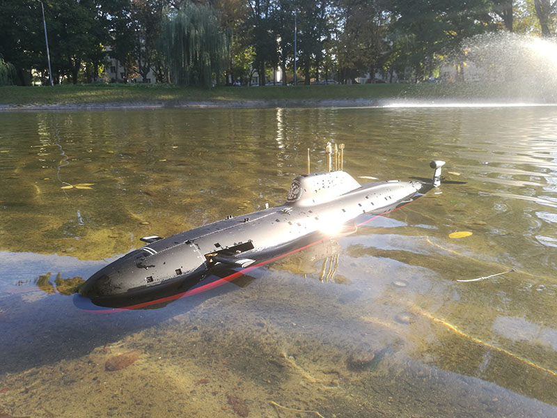
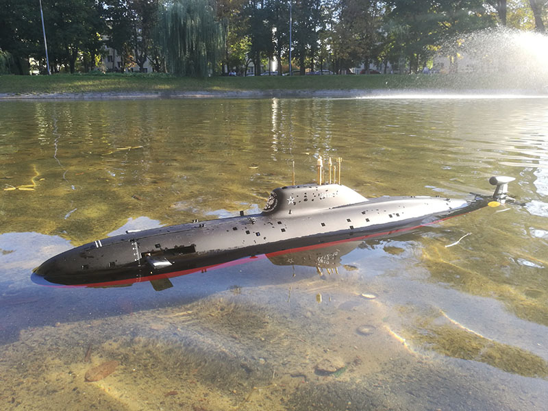
Trimming and maiden voyage.
The maiden voyage held place at Subregatta 2018 in Bratislava (Slovakia). Sadly I don’t have any photos from the initial run, cause during those first runs, my Akula lost its propeller (forgot to use the thread glue). I was not able to retrieve it and the model had to go in the box. Still had two other models so it wasn’t a big deal anyway.
Bellow you can see the photos from the second run – from one of my local parks. I’ve have bought a new propeller – 10mm smaller the the first one and I honestly think it runs much better. I don’t run my models fast and with the old propeller, the model was a like a underwater jet so not really my style.


Necessary and highly recommended modifications:
(Especially for the folks who plan to buy this thing!)
List of the necessary mods – at least in my opinion.
-
Changing the Ni-MH D20 power pack for something up to date like Li-Po lub Li-Fe. The Ni-MH packs are fine for the RX, but for powering the main motor and the piston tanks it’s a real fossil.
-
Complete replacement of the supplied lower rudder. The new one should be shorter for about 3mm (in height) and about 34mm LONGER (length). Without changing it’s height it will most likely brake off and without changing it’s length the model will be quite uncontrollable. New and older rudder comparison:
-
Auto pitch, auto leveller or pitch controller is a must. I can run my 2 meter Typhoon without one, I can do the same with ALL my models, except THIS one. It has to mean something…
Highly recommended modifications (aka making your life easier in the future):
-
Replacing the aluminium lid with a transparent polycarbon.
-
Propeller replacement from a supplied 65mm to a smaller: 55mm diameter. In my opinion 50mm would also work better then the 65mm too.
List of some seriously bad mods I found in the web when I was gathering informations before the build:
-
Adding a bow thruster in the bow (under the retract servos) instead of mounting it in the free flood areas in the stern. Why? Well because in case of the nozzle clogging (and believe me, that happens a lot during spring!), motor failure, or gasket failure (which will happen for sure after 8-9 years), the replacement of this element will be impossible after gluing the middle deck in place.
Last update: 28.05.2019 r.
Using any of the materials gathered here without the written consent of the author is strictly prohibited.