
Technology – The knowledge and the equipment you’ll need to construct and operate your radio controlled model submarine.
Table of contents:
– Submerging – absolute basics.
– Dive planes.
– Model types – static divers and dynamic divers
– Model submarine ballast systems
– The volume of your ballast tank
– Sealing the moving parts of your model – shafts, pushrods etc.
– Radio noise suppression
– Trimming
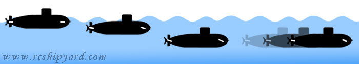
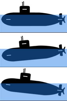
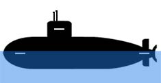
To understand how a RC model submarine dives you need to understand how the real submarines manage it, just the general idea.
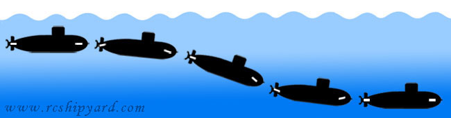
Real submarines have complicated diving systems consisting of many ballast tanks, trimming tanks, auxiliary tanks, emergency tanks etc. Everything is being controlled by lots of valves with lots of backup systems. All of those are connected with pressure tanks filled with compressed air, which is gathered and stored during the surface cruise. During that surface cruise submarine is in a state which is called a positive buoyancy, because its diving tanks are filled with air. When the dive is ordered, the upper vents of the ballast tanks are being OPENED which causes the tanks to flood with water through the bottom openings. Now the submarine has either neutral or negative buoyancy – it dives and can cruise under the waters surface. Finally, when the resurfacing order is given, compressed air is being blown into the tanks while the upper venting valves are CLOSED. That causes the air to push the water out from the ballast tanks through the bottom openings of the ballast tanks and the submarine becomes positively buoyant again – can cruise on the surface. Watch the animation on the right to get the general idea.
Diving planes:
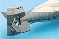
Submarines in addition to well known rudders are also equipped with something called “diving planes”. Diving planes look a little like horizontally placed rudders. There are two types of those: Stern (rear) diving planes and bow (front) diving planes. When the submarine is in a state of neutral buoyancy diving planes are used to control it’s pitch and the depth of the vessel. Diving planes manage to change the submarines pitch and depth only during the vessels movement and their efficiency is greatly effected but the boats speed. Lower speeds require bigger angular rates, higher speeds require lesser.
Bow diving planes are either placed on the bow (hull) or the sail (tower) of the submarine. Both mounting types have their cons and pros, most of the differences are rather tactical and as we’re making a model submarine, not the real thing, we don’t really need to bother with those. The only thing worth considering is that the bow dive planes placed on the sail won’t help us during the dive maneuver, in contrast to the ones placed on the bow. It because the “hull placed” bow dive planes are mounted closer to the water line and they submerge faster (or are always submerged like in most II WR boats) then the planes placed on the sail/tower. That allows us for faster pitch corrections – for example when diving in shallow waters. The bow planes efficiency is better in general, as they’re mounted further from the center of gravity of the boat. However, the diving planes on the sail give better stability during under water cruises and they’re generally safer from accidental damage during model operation or transport. I’ve learned that during my early years while operating the Robbe Seawolfs (conversions to static divers). The original design had the bow planes mounted on the bow/hull (Seawolf U1 in my shipyard) while in the second incarnation of that model (Seawolf U2, still in service) I’ve changed their location to the boats sail/tower. You can’t imagine better conditions to notice the difference – same model, just different bow planes locations. In the real full scale boats, after reaching certain speed the bow planes were either fixed in horizontal position or, if it was possible, they were retracted into the hull. Slight trim correction were then made only using the Stern bow planes.
|
|
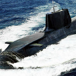 Diving planes (bow planes) mounted on the bow of the Vanguard class.
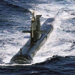 Diving planes (fairwater planes) mounted on the sail in the Collins class
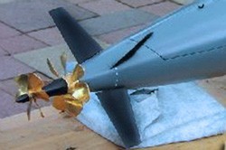
Stern dive planes also have their various types and their location may differ, they often work together with rudders too. They can be placed before or behind the propeller. The mounting can be classical – cross shaped or X shaped – with a 45 degree angle, which is then called the X-rudder system. Different stern diving plane types, even when so different by their look, generally give the same amount of control. In their case the rule is simple – the bigger they are, the stronger and faster reaction we’ll get. Submarines usually have two rudders, the upper one has no influence on the boats control while on surface. That’s why quite often, real submarines have the lower rudder in a different shape then the upper one. The lower one is shorten in height, but longer in width. That shape allows the submarine to park on the ground of the reservoir without damaging that important element. The X-rudders don’t have that problem as they’re placed angularly. Their work principle is a bit different however. In that type of diving planes, we cannot distinguish the rudders from the stern diving planes, as all 4 planes work both for changing the pitch and direction of the submarine. It’s worth saying that, in the X-rudder controlled model, it may be required a channel mixer onboard the model or one in the RC transmitter. Classical rudders and stern diving planes don’t require any mixers.
 |
 |
 |
In a full size submarine, at the very beginning of the dive maneuver* the stern dive planes are being slightly lowered, which causes the whole stern to raise a little. The angular change of the stern planes at that time cannot exceed certain values as to much inclination will cause the propeller to break the water surface and loose its efficiency – that would make the whole maneuver a lot more difficult (and slower). At the same time, the bow dive planes are being raised to “push” the bow of the submarine under water surface. The whole vessel begins to pitch down, and the propeller pushes the boat underwater. During that time, the stern diving planes are usually set into the neutral setting, until the desired depth is acquired. When that happens, the bow diving planes are being lowered causing the bow to move up and the stern diving planes are being raised to lower the stern. That setting is being kept until the submarine is in horizontal position again. When that’s finally achieved both planes are being set to neutral and the vessel continues it’s journey submerged. If the submarine is properly balanced – trimmed, then the further depth change is being done only by the diving planes, not by changing the amount of water in the ballast tanks.
*This description does not include the buoyancy change done with the ballast tanks, which happens at the same time.
That’s how it happens in general in the full size submarines. In our models the dive plane movements can be and usually are – much more simplified. Other types of ballast systems – not only those based on compressed air, are also possible. Still, I had to explain the absolute basics from the real size navy vessels, as the rules of behaviour (physics) for both, the real ones and models, are the same.
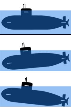
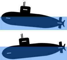
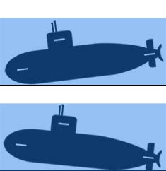
Dive planes of most RC Submarines with a ballast system (static divers) are being operated in a rather simplified manner. They just work opposite to each other, if the bow (front) planes are being raised – then the stern (back) planes are being lowered. If the bow planes are being lowered – then the stern planes are being raised. It’s easy to understand by analysing the animations below. Of course, if we have a RC transmitter with mixer functions, we can add a different much more complicated behaviour – for example dive planes angular movement can be limited as the model accelerates.
Animations showing the typical movement in a model Submarine. Both types: one with the bow dive planes placed on the bow and the second with the bow dive planes placed on the conning tower:
|
|
|
Some of the models are being capable to run at very high speeds while submerged. For such “speed runners” like for example the Russian Akula or the German type 212, automatic pitch controllers are highly recommended. What does it do and why does it help? As we’re controlling the model from a certain distance it’s simply not possible to act quickly enough with pitch corrections. Additional difficulties like distortion of the visual perception through the water surface also appear. That may be a cause for an unwanted resurfacing, or worse – hitting the floor of our water reservoir. To prevent such events a pitch controller was developed and produced by multiple vendors. It can help greatly to keep the boat horizontal during the submerged cruises, as it automaticity sends the signal to the dive planes servos, when it senses an unwanted pitch change of our RC submarine. Of course the signal from the RC transmitter has the priority over the automatic signal, allowing for a desired depth change or surface/dive manoeuvrers. Some people compare those devices to the RC airplane autopilots or helicopter gyros and they’re right at some point – as their function in a model is the same, however those are completely different devices and cannot be used in our models.
Types of the submarine models – static divers and dynamic divers.
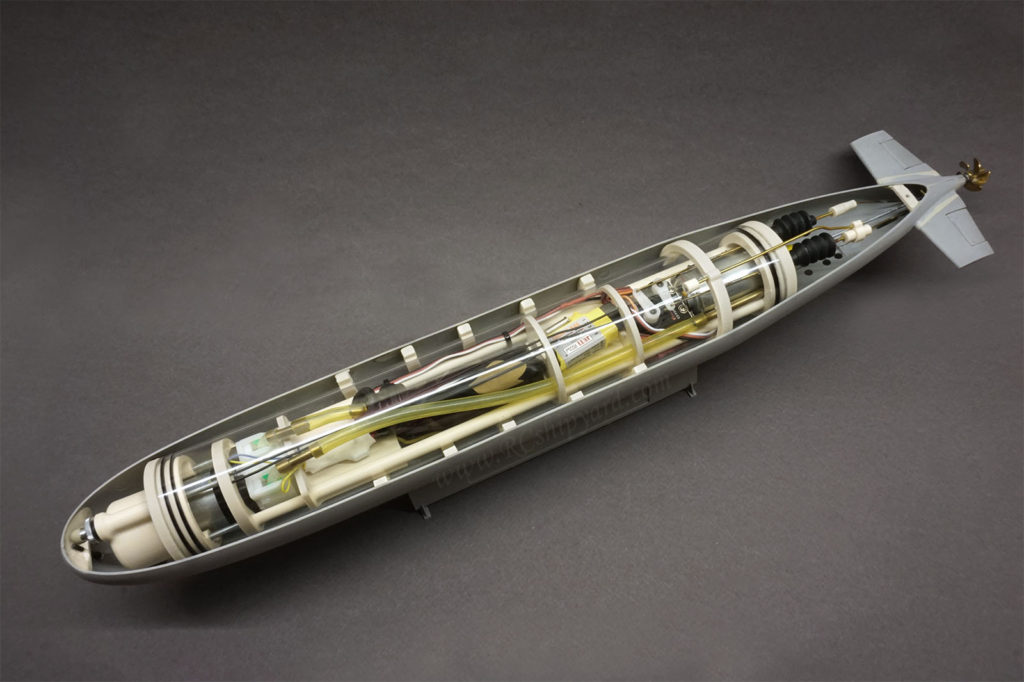
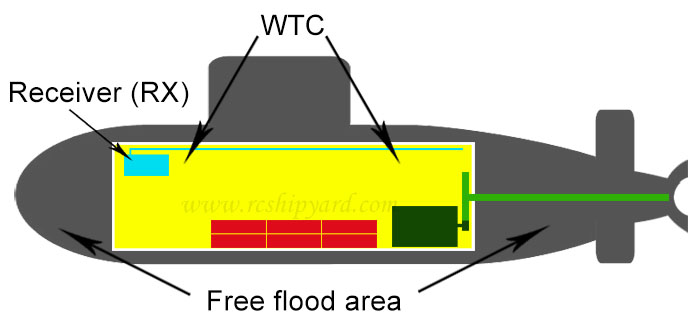
First of all, you need to know that when building a RC model submarine you don’t watertight all of it. Like the real things, most of the models have two hulls. The outer hull is giving the model only it’s shape and it’s not watertight. The inner hull is watertight and often capable of withstanding great water pressure. The space between both hulls is not sealed and it’s called the “free flood area”. The watertight section holds all the electronics, most of the mechanics an it’s called a WTC – Water Tight Container or Water Tight Cylinder.
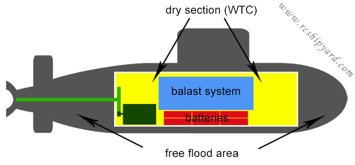
A drawing describing the idea above and a real model with a cylinder fitted in below:
In General, there are two types of RC model submarines: dynamic divers and static divers.
First type – the dynamic diver is the most simple model submarine you can build or operate. The work principle is based on the idea that the model has only slightly positive buoyancy and when you wish to dive you simply accelerate and push your model underwater using only your diving planes. Until the model is in motion and diving planes are in the dive position the model runs underwater. As soon the model slows down or you’ll set your diving planes to surface position it will resurface. Its resurfacing looks a little like a plastic bottle popping out of the water. Such type of models need to have much stronger motors for their rather large and aggressive propellers and much bigger diving planes operated by stronger servos.
Second type is called a static diver. Those are models with an active ballast system allowing for a buoyancy change and submerging even at full stop – that’s why they’re called static divers. Their diving manoeuvrers look much more realistic – like the real boats and their constructions are much more complicated and time consuming. They also require more time for trimming as you need to set the surface trim as well as the submerged trim (described further). There are many types of active ballast systems for the static divers. I’ll will explain some of them here – the ones most popular and reliable.
-
Ballast systems based on pumps (closed or open systems)
-
Ballast systems based on air compressors
-
Ballast systems based on gasses (liquid or compressed)
-
Ballast systems based on pistons.
The above list may seem a little hard to understand, so it may seem easier to read as a graph:
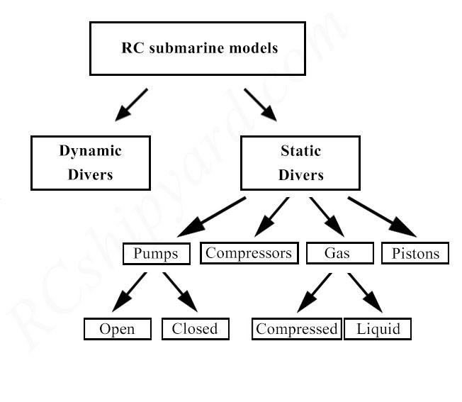
Model Submarine Ballast systems:
Ballast system based on a pump (open)
One of the simplest active ballast systems you can create. Easy to assemble and to gather all the necessary elements. To submerge the model you simply open the valve and turn on the pump which quickly fills the ballast tank with water. The air from the ballast tank escapes through a small diameter vent – usually a thin (not thicker then 2mm/0.08 inch) tubing mounted in the sail and hidden between the periscopes and antennas. When the ballast tank fills up completely we shut down the pump and close the valve. The model should now have a slightly positive or neutral buoyancy – in a perfect scenario only the periscopes and the vent (something like a snorkel) are above the water surface. Further depth change is being made only by the dive planes. To resurface the vessel the model has to break the water surface with the tube/snorkel first and that should be achieved by throttle and dive plane manoeuvrers. Then, we open the valve again, start the pump – just in a different direction, which “sucks pit” the water out of the ballast tank causing the model regain positive buoyancy. The biggest disadvantage of this type of ballast system is limited possibility of parking the sub on the ground. In case of loosing the main drive (for example motor or ESC failure or loosing the propeller) model might have problems with resurfacing if it’s to deep. This diving system is used mostly in smaller simpler models – good for starters
Hints and warnings:
– You can use any type of two way pump (or two sets of one way pumps). For example geared or peristaltic pumps, however using a peristaltic pump will make the dive longer as those pumps are slower – but it will also overcome the requirement of using a valve. In both scenarios It’s worth considering placing a filter on the pumps water inlet.
– Like I wrote earlier, the tube/snorkel should be really thin, why? Because, if you find yourself unable to reach the surface using your drive, you should still be able to suck enough water from the tank (creating under pressure in it) to resurface, before the pressure will be equalized by the water being sucked in the tank by the thin vent/snorkel. This system can have the valve placed between the tank and the pump (like in the animation above) OR between the ballast tank and the vent/snorkel. However valves being capable of sealing air flow rather then denser water, are much harder to find or manufacture.
Ballast system based on a high pressure pump (closed):
This ballast system is based on a high pressure pump capable of filling a closed tank without a vent and the valve being able to hold that pressure. To submerge the model you open the valve and turn on the pump which fills the ballast tank with water. The more water is the tank the harder work the pump does – it pulls more power. The filling of the tank slows down while the pressure increases and will stop at some point. In this type of ballast system it’s impossible to fill the tank completely. With a very efficient pump it’s possible to fill it to 3/4 or 2/3 of the total volume and you need to remember that when calculating the ballast systems size. It’s also worth mentioning, that actually it’s not the water is being pressurised, but the air that’s trapped in the tank. When the model finally submerges we shut down the pump and close the valve. What’s important is that, you don’t need a two way pump for this system. A one way, high pressure pump will do the job as long as it has a free flow when it’s turned off. The pressure in the tank can push out the water from the tank itself. It’s a great advantage in case of a pump failure, however it’s also the only advantage of this system. The difficulty with this kind of ballast systems are finding a high quality pump, a good strong valve and that it needs much more power then the other systems. In my opinion this system was never worth considering, as you can have a simpler and cheaper alternative explained below.
Hints and warnings:
– If you’ll forget and keep the pump running the results can painful. I don’t think it’s possible to rapture a good quality pressure tank, but it’s very easy to brake or over heat the high pressure pump. The same goes for the pump driver (if there’s any).
Ballast system based on a pump with an elastic ballast tank (closed):
This diving system is based on mother nature herself! Works on the same principle as the system above, but with an elastic ballast tank, which eliminates the need of using a high pressure pump. The elastic ballast tank can be made out of many things, balloons (only latex ones are reliable however), emptied medical drip bags, or drainer bags for urine (best in my opinion). The biggest advantage of this system is the ease of gathering all the elements and it’s price. The water still compresses the air here, but in the whole WTC – which means more space – less compression (smaller pressure) and less problems. The pump does not need to be a high pressure one, all of the model fuel pumps will manage. However as the pressure of the air surrounding the elastic ballast tank is much weaker then in a system with a closed tank, we need to use a two way pump to empty the ballast tank actively. Again, if we’re using a pump other the peristaltic, we’ll need a valve, but again as the pressure here is low, it’s extremely easy to make one ourself. For those who worry to much it’s worth mentioning that an overfilling sensor/switch is not hard to implement in this system too. With simple wiring, the switch will cut of the power to the pump, when the elastic tank is full, but will still allow to turn on the pump in reverse to empty it. Some more complicated systems can have electronic pressure sensors which will stop the motor, if the tank is full and they also monitor the battery level, not allowing to fill the tank if the battery is almost empty (Thunder Tiger ballast pump driver). A very nice pros for this system is that in an event of a pump failure (if we’re using free flow pump) the pressure will very slowly empty the tank enough for the model to resurface slightly as soon as you’ll open the valve. Slightly, as just under the water surface, which is still a lot better then on the bottom of the lake.
Hints and warnings:
– Geared pumps need to be placed under the waterline of the model for its easy flooding as they have poor sucking efficiency (still they’re capable of quite a compression). It’s easy for the pump to catch some air bubbles and placing it under waterline helps a lot to get rid of them from the system quickly. Sometimes a big air bubble caught in the tubing can disable the pump efficiency completely.
– Filters! Even a small rock can block your geared pump and stuck in the tubing.
On the right, you can watch very old clip showing a bladder system working in my Robbe Seawolf U2. Year 2006 if I’m not mistaken.
Recirculated compressed air ballast system (RCABS):
RCABS – Recirculating Compressed Air Ballast System is a diving mechanism based on a small electric air compressors and elastic bladders. Usually it consists out two bladders hidden in the free flood area of the model, one in the bow and other in the stern. Systems with a single bladder in the centre of the model are also quite often, but they demand a special type of WTC – divided into two connected parts with a third place for the bladder in the middle of the WTC. The air compressors move the air from the WTC to the bladders causing the model submarine to resurface. When the bladders are full the compressors are being shut down and the valves close allowing of holding the air in the bladders positive buoyancy. A big advantage of the system is the possibility or fine trimming the water line of the model – it’s done by filling or emptying the bladders slightly. This system brings some controversy into our hobby as it has both great supporters and even greater opponents. The main objections against this system are that the model with out the bladders filled with air has a negative buoyancy, which some find to risky. If I’m correct the system was invented by dr. Art Broder, but it’s hard to confirm that information now, as the site I’ve read it about him is long gone. Personally I’m in the “against this system group” BUT, if you already have some small electric compressors (for example from electric blood pressure monitors) it’s worth trying the modified version of this system described below.
Hints and warnings:
– Electric valves for pneumatic operations which will not have contact with water (like in this system) are easy to obtain from the pressure monitors too or on Ebay. Just remember to choose the type which is normally closed and opens only when you apply power to it. It’s worth mentioning that the small electric compressors often have no airflow while they’re off and they’re a one way thing. Additional tubing for the valves may be required.
– Improperly done, this system will create an under pressure in the WTC, which may suck in water even through the best seals.
Reversed recirculated air ballast system (RCABS-R):
RCABS – R (Reversed Recirculating Compressed Air Ballast System – ) This system is almost identical like the normal RCABS but it’s principal is reversed – here we inflate the bladders when the model is still on hard ground. You simply blow some air into the WTC by a hidden valve, the air fills the bladders (like blowing air into a childs balloon). When we’re happy with their size/pressure we close the valve and put the model in water. The model now has a positive buoyancy and if we wish to dive we need to turn on the compressors which will compress the air from the bladders to the WTC. When the bladders become empty the valves are being closed and the model submarine submerges. For resurfacing we simply open the valves and the higher air pressure fills the bladders again. This system requires a special valve in the WTC for creating overpressure in by blowing air into it. Additional advantage of this system is that the WTC is always a little over pressurized which helps to keep the water out.
Hints and warnings:
– Small electric compressors are quite cheap and easy to obtain on various hobby sites or from mentioned earlier electric blood pressure monitors.
Compressed air ballast system :
Almost the real thing! A system based on a principle identical to the diving method from the real submarines. The ballast tank has a vent, with a valve – the “A” valve in the animation above. When it’s open, the ballast tank floods through the openings in it’s bottom and the model submerges. After that the “A” valve is closed and you can run your model on a submerged patrol. When you want to resurface the model, the “B” valve is being opened and compressed air, stored in a special high pressure tank, is being released into the ballast tank causing the water to be pushed out through same button openings. When the tank is finally emptied and the model runs on surface the “B” valve is being closed. Now you need to fill the high pressure tank with air again. For that you open the “C” valve and turn on the compressor. It sucks the air through the snorkel and stores it in the high pressure tank. When a desired pressure in the pressure tank is gained, the “C” valve is being closed and the RC submarine is ready for another dive. It’s the most complicated and hard to make diving system you can assemble in your submarine. There are no kits with a such a systems available. This system is very efficient in the real submarines, but it’s ideal for a use in a model. It requires a lot of expensive parts – high pressure air compressor., high pressure tank and some really good quality electric valves and scratch build electronics with pressure sensors. It also requires pressure reducers and quite a lot of RC radio channels plus some really good programming skills. It’s a system for big boats only as it takes LOTS of space in the WTC. If you dream about a monster size model submarine and you have a big budget connected with lots of engineering knowledge, then the system might be for you. Personally I’ve seen only two of those in my life and it’s my holly grail. I hope I’ll be able to make one some day.
Hints and warnings:
– With a proper shape of the snorkel, the “C” valve can be a simple-one way automatic valve.
– Be sure to check if you’re not creating the under pressure or over pressure in your WTC when the compressor operates, as such an error can be catastrophic.
Ballast system based on a liquid gas:
Avery popular system in the USA, as WTCs based on that system are being manufactured by David Merriman – model making legend. Personally I was so influenced by his work, that I’ve made my own WTC with that system in my Revell VIIC “Wolf pack” model. A well designed liquid gas ballast system gives great possibilities and can be a lot of fun to watch. The diving principle is the same as in the compressed air ballast system – the ballast tank has a vent valve. As it’s open, the ballast tank floods through the openings in it’s bottom and the model submerges. After the model is submerged the vent valve is being closed. If you want to resurface the model, the gas valve is being opened – the liquid gas decompresses and changes it’s state into airborne as soon as it reaches the ballast tank causing the water to be pushed out through button openings. When the model finally surfaces the gas valve is being closed. The one thing you need to remember is that you have a limited number of “shoots” in the gas tank and after a number dive/surface manoeuvrers you’ll need to go offshore and refill from a bigger gas cylinder. There are also European systems based on CO2 cartridges, those are a little more expensive to buy/make yourself, as CO2 is stored under a much bigger pressure and it requires more robust installation and pressure reducing valves. Still those are two systems working on almost the same basis. One is based on a liquefied gas which you refill from a bigger cylinder and in the other system you simply change a small cartridge to another and dispose of the empty one. In the end it means that both of the systems require extra cost to run. Both have some other advantages however. They allow for use of pneumatics as retracts mechanism and other realistic features like pushing out torpedoes from the tubes or even gas powered rocket launching systems. In my opinion the liquid gas system is cheaper and safer then the CO2
Hints and warnings:
– While developing a liquid gas system, you need to remember that the weight of the gas tank changes with each surfacing maneuver as the propellant runs out. It’s a good idea to mount the gas tank in the center of gravity of the model, as if you don’t, it may cause to pitch the model to bow or stern. Models often have a single ballast tank, which should be placed in their center of the gravity already, that means, that the gas tank should be placed in the ballast tank. One tank inside another.
– Some of the liquefied gasses are flammable and should be avoided, remember to read the gas composition label before use.
– CO2 cartridges can be dangerous if used incorrectly, please take extra caution while dealing with them as they can deal serious injury.
Ballast system based on a piston:
The system itself looks a little like a giant syringe sucking and pushing out water to change the buoyancy of the vessel. The piston is powered by an electrical motor moving a threaded rod by a gearbox. This system is capable of operating on a much bigger depths then the other diving systems. In my opinion, a well designed piston system can be very precise, maintenance free and most reliable diving method in a radio controlled submarine model. What we need to remember is, that it requires very tough and stiff WTC, as the moving piston can create enormous over pressure in the dry hull. I’ve seen plastic conversions and even some fibber hulls getting ripped like paper by the pressure from inside – created by the backing up piston. If you intend to use this system be sure that the hull you’re fitting it in is capable to sustain such pressure. Some of the systems are simple “empty-full” type, other give the possibility to stop at any moment during the feel/empty operation. The best ones however are the ones controlled by microprocessors and are capable of fine trimming the end stops of the piston tank (or tanks) giving not only the possibility to change “on the go” the models underwater trim, but also to trim it bow or stern heavy. This gives a model maker a great advantage in the trimming part of the model built. On European market you can also find piston tank drivers equipped with a digital pressure sensor, those are capable of holding the desired depth when the model is at full stop.
Now the disadvantages… Well, quality can cost a lot. If you intend to get a reliable, ready to use kit, you’ll have to deal with a price in hundreds of Euros – about 450 Euro for a kit of two piston tanks (0.5l/17fl oz capacity) with a microprocessor driver for them. There are piston tanks on Ebay from Chinese manufacturers for less then half the price, but their quality can be questionable. If you’re looking for a reliable system, which will work for tens of years with almost no maintenance then, you should go with the European ones. The principle of the system is quite easy, so if you’re not afraid to make something yourself, then go ahead and try yourself. The trouble begins when you want to have a microprocessor driven unit with a digital pressure system. Then you’ll need both hardware and programming knowledge.
Size (volume) of the ballast tank:
“The volume of the ballast tank must be sufficient to compensate for the buoyancy force“
A sentence straight from the book, dry and enigmatic.
I will not discuss the buoyancy force here, neither do any difficult and unnecessary mathematics of calculating a perfect displacement model. I’ll just try to answer, one of the most common questions I get, in a simplest possible way. That question is:
“What’s the size of the ballast tank I’ll need?”
While constructing a model submarine, the volume of the ballast tank is determined by many variables. Bo when we start analyse everything, we’ll finally get into to conclusion that it depends mainly on the size of the WTC. Yes – WTC, not the whole model. The models hull is only an extra load (extra weight) in a fancy shape. In many models, the shape/type of the hull easily allows us to change that extra load into extra buoyancy too, but that’s something for the “Trimming chapter” which you’ll find later on this page.
For model submarine makers, the simple rule is, that when you want to run on surface you need to weight less then the water you’re displacing. If you want to run submerged you need to weight equal or a little more then the weight of the water you’re displacing.
Ok! How much water I’ll be displacing while submerged then?
Let’s forget about the hull for a moment, it has negative buoyancy for sure anyway. If your Water Tight Compartment is cylinder shaped. Just calculate the area of the WTCs endcap and multiply it with the WTCs length. That’s the volume of water you’re displacing.
Example:
– Let’s keep things simple and remember that 100ml of fresh water = 100 cubic centimetres = 100gram
If your cylinder is a 5cm in diameter and 40cm long, it means that: 3,14 * 2.5cm squared * 40cm (π r2 * h), will give 785 cubic centimetres of volume – this is the amount of displaced liquid while fully submerged.
Okay, I know my displacement, what I can do with it?
Now you can calculate the weight needed to submerge, so 785 cubic centimetres of water = 785 grams. That means that your WTC has to weight about 785grams to submerge.
Ths also means that the weight of the WTC with all it’s electronics, mechanics, batteries and with the hull all together, has to be less then 785grams to keep the model more or less on the surface.
That means, that if your WTC with all it’s electronics, mechanics, batteries, together with submarines hull and but with an empty ballast tank has a weight of (for example) 700g, you’ll need a ballast tank capable of holding 85g of water, which equals to 85cc=85ml.
If your model gains 85ml of water, it will weight 785grams and it will submerge.
So 85grams is the answer to your question in this example. Just to be on the safe side I would say that’s your minimal ballast tank volume. Always add 5-8% to your calculations and you’ll be safe for sure.
There is one more method of calculating your ballast tank volume which you should know about. This is a great simplicity and all the physic teachers would probably throw you out of the class for that, but…
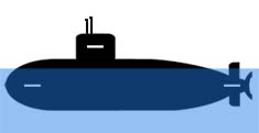
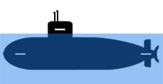
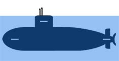
The volume of your ballast tank will always be equal to the volume of WTC which remains above water surface while running on the surface. Why I tell you this? Two reasons. One is that some of you might get a second hand model without a ballast system or you might be doing a conversions from dynamic diver to a static diver with the WTC already glued into the hull. The second reason is that those WTCs can have creative shapes and it might be really hard to calculate their total volume. Calculating only the part remaining above water is often a lot easier. Look at the picture for a better understand of that.
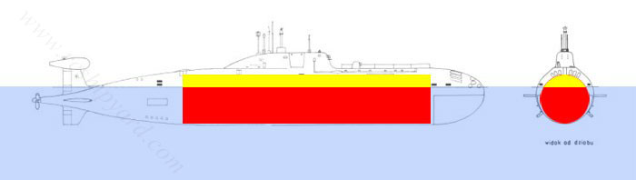
This is a models drawing with a WTC inside. The blue colour marks the water of course, also it shows you the correct waterline of this particular vessel. The red part of the WTC is the part which is always underwater – while model runs on surface or submerged. The yellow part of the WTC is the one which is above the water while the model runs on surface and that’s the volume of our ballast tank needed for this model to submerge.
Examining the picture it’s hard not to notice one more thing. The smaller the yellow part will be, the smaller ballast tank will need. This is why it’s always a good idea to keep the WTC as smallest as possible and in 90% of scenarios it’s better to place it lower in the hull rather then higher.
Methods of sealing shafts and pushrods:
Pushrod sealing:
I get many questions by @ where people ask me how to seal servo pushrods and main motor shafts.
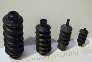 Most folks figure out their sealing method of the shaft themself, however they have certain problems with finding information how to seal the pushrods. There are quite a few methods of dealing with this problem. The type of seal should be matched to the model type, size and sometime even to the ballast system used. A very important thing is the size of the pushrods we’re going to use – bigger models have thicker pushrods and stronger servos with bigger arms, while smaller ones, like plastic conversions, use micro servos with thin pushrods. One of the most universal methods of sealing the pushrods is a rubber bellow. On the photo I’ve gathered four of them in various sizes: from 35mm up to 65mm, for diameter of the pushrods from 1mm to 5mm. Usually the bigger the bellow – the thicker its rubber, therefore more torque will the servo need.
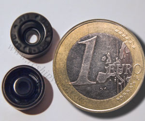
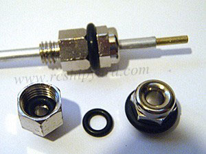 Other well known method of sealing the pushrod is an o-ring (a pair actually), placed in a hollow bolt with hexagonal body. It’s a very durable method of sealing, but usable only for pushrods with a 2-3mm diameter. O-rings need to be lubricated inside for lowering the friction as much as possible. This method is somehow similar to the old “grease box” technique, but with additional o-rings, which makes it much more safe. This method is not suitable for any rotating connections as the bolt/screw would simply loosen with time, leading to a small catastrophe. One really big advantage – no limit in the length of the pushrod in contrast to the rubber bellow.
Shaft sealing:
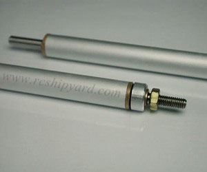 The best method of of sealing a shaft is… …buying a whole shaft – a high quality one. That’s the truth. Sadly, nowadays it’s really hard to buy such as more and more companies move their factories to china and the quality gets worse. On the photo you can see high quality shafts made by Marx. Made out of stainless steel on a cnc machine, with double bearings, including vibration dampening and a double lip seal on each end. Their quality is really astonishing. They’re maintenance free and don’t require any additional lube. They do have one disadvantage however, (except the price of course) – Marx as company is gone and it’s really hard to buy those. So what can we do about it? Well, traditional shafts with a nylon/teflon bearings and lots of thick grease inside do the job too. They just require stronger motors, to fight the additional force caused by the extra grease and occasional reapplying of it.
 Simmering, oh boy… I have a history with that little thing! At first I’ve hated it so much! I just couldn’t understand how it can be so popular with the other guys. Well, I was young, I was wrong, as now I love it and find it very reliable. Not only for sealing the motor shafts but also with geared pumps. It’s easy to get and easy to use. A well designed model – with an access to that type of seal for occasional lubrication will last years. I used to replace this seal every two years in my VIIC. Then I’ve stopped to see how much time will it take before it will fail. Well, it now has 6 years and it’s still keeping the water out. The one thing which we should remember is that this seal does not like high rpm motors.
 PVC tubing covering a sleeve and a part of the shaft. Something not many model makers know or prefer, even when this method is used for many years by one of the leading submarine kits manufacturer – Engel. The design is simple, but still there are few things which we should know about it. The tubing is not cheap Chinese made, like lots of those sold in the DIY markets, it’s not silicone fuel tubing from the model hobby shops either. The best ones is European made and medical grade, but high quality technical will do the job too. The diameter has to be carefully selected. There isn’t much choice on the market when it comes to that, so often you need to match the shaft diameter (and it’s sleeve) to the tube, which sounds a little odd, but that’s how it works. The advantage of this method is obvious. It’s easy to check and replacement takes about 2 minutes. If we buy a 2-3 meters of that tubing we’ll have sealing materials for a lifetime. Just remember to use some Vaseline when placing the seal in place.
Radio noise suppression:
Except the rare electronics designed especially for model submarines – pitch controllers, depth keepers and ballast tank drivers, there are no such things like electronics designed especially for model submarines. Most of the items we use were designed for RC aircrafts, some for general modelling purposes. Two way electronic speed controllers (ESC) with water cooling are very rare and expensive. Sometimes it’s even hard to find an ESC without “brake”, as most of them were designed for RC cars. The same story goes for a very crucial element of an every RC model – the radio receiver (RX). The engineers who designed them had that nice idea that the model makers will mount their receivers as far as possible from electronic noise generating parts, like ESCs or brushed motors. They were also pretty sure that the RX will have a fully extended antenna, freely waving in the air (rc planes) or extended straight up with a plastic tubing like (rc cars or surface boats). What they did not thought of, is that someday, someone, will get an idea of a model submarine, with that small watertight cylinder, where you cannot extend the antenna and where the RX is always close to something. And that’s why you can get a 2 miles (3.2km) of range with your RC plane and only about 200ft (61m) with your model submarine. By writing 200ft, I mean 200ft at best – with a carefully selected places for electronics and with enough noise suppression.
Model submarines are a tough place for the electronics. Moisture, quick temperature changes and lack of space to keep everything separated plus thick hulls and surrounding water itself. I’ve seen models so poorly assembled, where even slightest motor operation was causing servo jitter. Such models were almost completely out of control 10ft (3m) offshore already . On other hand, I’ve seen model makers who were able to operate their models even further then 60-70m (197-230ft). Where their electronics different? Quality of elements course matters, but those models mostly just had nice and clean wiring installations with suppressors.
Sadly, the 2.4GHz radios, which became today standard are completely useless for us, as this frequency has almost no ability to penetrate water. The only choice we had for now were the traditional FM frequencies – 72 and 75MHz (USA and Canada) and 35 and 40 MHz for Europe. Slowly some people start to experiment with 433MHz radios, but I can’t tell you about those yet, as I’m using them only for long range aerial drones. Remember to check your local laws to see what frequency you can use.
 Our radio range is greatly effected by the type of the receiver and how we’ll place it’s antenna. The antenna is just a piece of wire, but it’s length has been matched to the frequency it’s using, so unless you know what you’re doing do not modify it’s length. The antennas purpose is to “catch” the correct radio waves and pass them to the receiver. Sadly it’s “catching” lots of radio noise too, that noise has to be filter out by the receivers electronic and this is the part where quality really matters. A good quality receivers are made by Futaba, Schulze and Corona – they all make (or used to make) two type of receivers – dual conversion and single conversion. Whenever possible always go for the dual conversion type. They’re better in every way, but they’ll might be pricey. When placing your receiver in the model the rule is quite simple, avoid placing it next to the ESC, electric motors and wires – especially high current wires. Those 3 things can severely cut your range. Almost the same rule applies for the antenna placement – try to spread it from one end of the vessel to another, yet avoiding as much as possible electric motors and electronic speed controllers. High current electric wires placed in parallel with the antenna are a serious range cutters too. Antenna glued to metal or carbon fibre objects can be also affected. There are situations when it’s worth to place the antenna in the free flood area (where it will be wet, but still safe) – in the model, but outside the WTC. It does the job only in certain situations however – when the construction of the boats WTC allows disassembly with a wire sticking out of it. Before placing your antenna in the free flood area you need to inspect it carefully to make sure, that it’s plastic covering is not damaged and you need to waterproof its end too. The wire in the antenna cannot have contact with water, as it will bring range problems and we will gain nothing. Lastly, one more advice – if you want have a long, fail free operation of your receiver place it on some kind vibration isolating foam. After certain time vibrations can cause micro cracks in the electronic paths and therefore receiver failure. Correct receiver and antenna placement can be a real pain in the a**, but correctly done will pay of with years of safe model operation.
Radio range in a model is greatly affected by negligence with electric installations too. A spaghetti made out of wires can generate enough noise to cut our radio range in more then half. Remember – think how to run all the wires before placing your electronic. Don’t extend your servo wires unless it’s really necessary. If you such a situation occurs however, use a ferrite core/rings and turn your excess wire around the ferrite core. Some better brands of ESC and BECs have ferrite cores implement by their manufacturer – just in case. High current consuming items like pumps, pistons, ESC and electric motors should have shortest possible wires. If you have one of those situations with a battery in the bow and the ESC in the stern, it’s worth to braid or at least twist the (V+ and GND) wires tightly against each other. Believe me – it works. Higher quality servos, especially the ones marked as high torque have twisted or braided wires already instead of the normal flat ribbon.
|
|
|

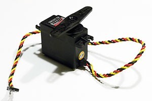
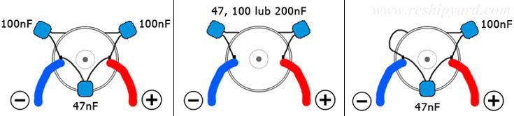
Brushed electric motors are still being used in model submarines cause of various reasons. First of all their slow rotation is way more smoother then slow rating brushless motors (no cogging as with brushless motors). They’re also very cheap and two way speed controllers for brushed motors are also a lot cheaper then the ones designed for a 3f brushless motor. We really don’t need all the power that the brushless motors can provide. They do have one disadvantage however. The motors brushes cause electrical noise and this is why all the motors should be suppressed before operation in a submarine model. We suppress the motors by soldering proper capacitors. The best ones for this task are the ceramic ones, but as I know from my experience with the typhoon, other types do the job too! Before soldering fresh capacitors, it’s worth to grab a flashlight and visually check the inside of the motor as it can already be suppressed from the factory. Good quality motors are often already suppressed with two capacitors. Then it’s up to you, will you leave it with two caps (which is quite good already) or add a third one for best effect. If you want to “see” a difference between a non suppressed motor and a suppressed one, theres a neat trick to check it. You just need an AM/FM music radio and turn on the motor in close proximity to it. The unsuppressed motor will generate enough electronic noise that you’ll hear it in the speakers as interference.
Trimming the boat.
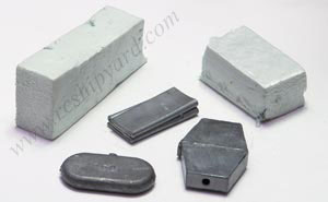 Trim – it’s simply balancing your model ship by distributing weight to keep the hull floating levelled in the water. However when it comes to model submarines it gets a little more complicated. Submarines need two type of trimming – surface trim and a submerged trim. Surface trim usually affects the submerged trim. All of that gets even more complicated, if we care about a correct water line. For this construction phase we need weights (lead or stainless steel) and hard/stiff foam like styrofoam. We’ll also need something to keep the things in place, glue or water resistant double sided tape. Trimming is a rather boring and a time consuming action which is sadly essential for a correct submarine model operation. I cannot give you details how to trim your own model, but I can give you some general guidance and the correct order of your actions. Remember that trimming should be done to a fully finished and painted submarine. Bellow you’ll find my guide how to do it painlessly as possible. Just remember that sometimes, it’s worth taking a step backward and correct something, rather then struggling with every next step.
Before the trim process:
– Get some kind of water tank, if the model fits your bathtub it will do just fine. Make sure the model is watertight and that no air bubbles are coming from it.
– Press the model underwater with your hand and move it forward and sideways quite roughly – that way you’ll get rid of air bubbles trapped in nooks and by the surface tension.
– Fill the ballast tank and empty it about 3 times – you’ll be sure that there is no air trapped in the system. The less air is trapped in the model the better result you’ll get.
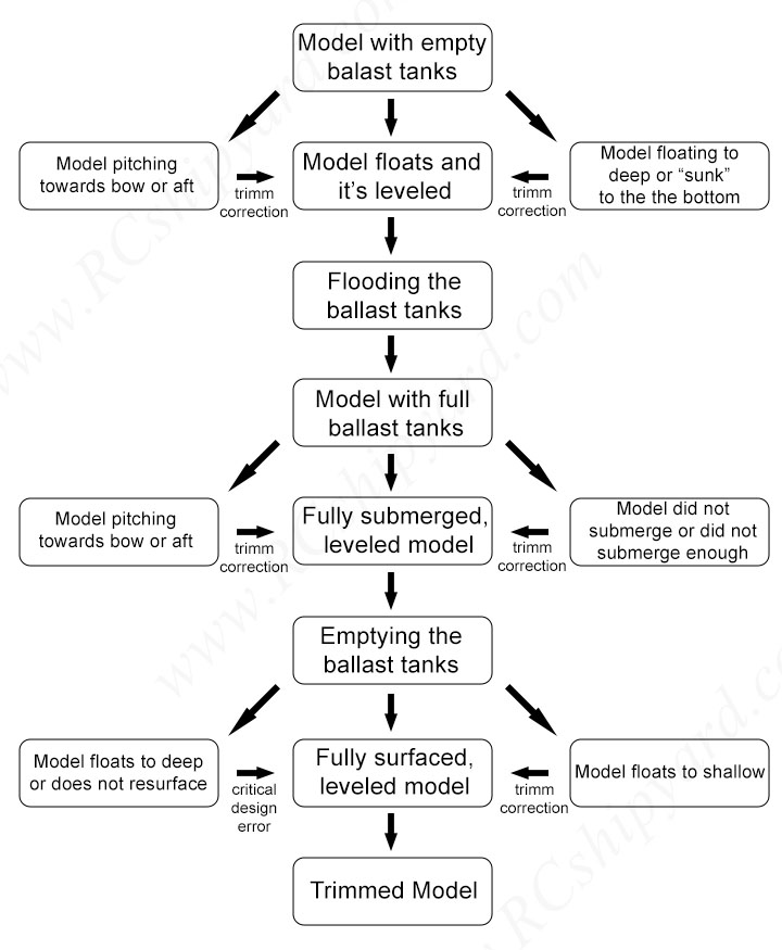
Trimming – the processes itself:
– When you place the model in the water there are two scenarios possible, both with completely different actions, so better keep attention which is which:
-
Scenario 1. Model floats – has a positive buoyancy with an empty ballast tank.
-
Scenario 2. Model does not float and “drops” on the floor of the tank – negative buoyancy with an empty ballast tank.
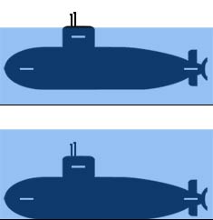
Scenario 1:
– model floats, ballast tank empty – before additional lead ballast or styrofoam.
– So you’ve placed the model in the water and it floats. If it’s levelled then great, but maybe it’s pitching to bow or pitching stern? We correct it’s pitch by placing lead (or steel) weights in places which are to high in the water. Extra weight should pull those parts deeper into water and slightly raise the opposite end of the submarine.
– If there are parts of the model which are to deep in the water, then you’ll need to add the styrofoam. You need to place it in the free flood area, under the water line to add some buoyancy.
Scenario 1:
– filling the ballast tank.
– Model (or part of it) does not submerge. First check the pitch of the submarine. If only the conning tower stays above water and the hole vessel is levelled, then press the model gently under water and watch it behaviour. It may not get back to the surface which meant that there was some air trapped somewhere and you don’t have worry about it as it will always be pushed away by the models motion during normal operation. If the model gets back to the surface slowly the you’ll need to ad some extra weight on both it ends. Sadly It will influence your surface water line (the model will sit deeper in the water) and you cannot do anything about it, as the ballast tank is simply to small. If possible, make the ballast tank bigger and repeat the whole trimming process.
– If only a part of the model is submerged – for example the bow, while the stern is still partially above surface, then you need add some lead on the stern section. It will also influence your surface trim.
 – Of course the most desirable situation is when you fill the ballast tank the model parks on the floor with out any pitching. That would be the end of the job here. Maybe some minor trimming during the maiden voyage still would be required, but that sometimes depends on the hulls shape.
Scenario 1 – model floats, ballast tank empty – after additional lead ballast and styrofoam.
After all that adding and removing lead ballast/styrofoam you’ll need to empty the ballast tank completely and check the surface trim one last time.
You will get such possible situations:
 – 1. The boat is surfaced and if you were thorough (and had a bit of luck of course) the model should have more or less correct waterline. Waterline is correct when you can see the submarines deck and at the same time the propeller is fully submerged. If both of those are ok, then you’re ready for your maiden voyage. There is also something called “a correct historical/scale waterline” and that’s getting the water line like the original vessel has/had – if you want that then you’ll need to act more with lead/foam.
-2. Model with an empty ballast tank is only partially surfaced. It’s one of those bad situations which you can get – most likely it’s a design error. Either the ballast tank was calculated incorrectly or the WTC is mounted to high in the hull. Both are serious errors and hard to correct. Of course, they’re only cosmetic, so if you don’t mind the weird look and running your model only partially surfaced it’s alright to use it.
– 3. Model with an empty ballast tank is surfaced more then it should. It’s one of those “not really correct”, but still quite good situations. If the model is levelled and the propeller fully submerged then you can go for your maiden voyage. If you desire a correct scale/historical waterline or the prop is above the water level, then you’ll need to act. Basically you add lead till you’re happy with the water line, keeping attention to boats pitch. If you have a system with a ballast tank which you don’t have to fill up in 100% – for example: the elastic ballast tank, high pressure ballast tank, then adding lead should not affect your underwater trim, you will just need less water in the dive tanks, which is generally good as it makes the model submerge faster. However, if you have a piston tank ballast system or compressed air ballast system with automatic valves, then adding lead will change your submerge trim and most likely you’ll need to add foam above the water line (as model will drop like rock with that extra lead ballast and a full tank).
– 4. Most common situation you will likely have is a bow or stern pitch. Again, you’ll need to add extra lead ballast where the boat sits to high in the water. This will have an effect for your underwater trim so it corrections will need to be done. When you’ll finally be happy with your surface trim and the water line, then you’ll need to do some submerged trimming again, by adding some styrofoam (like I’ve described earlier). You just need to remember to place that foam above the water line, when surfaced.
Scenario 1. OPTIONAL STEP
Neutral buoyancy – not achievable for all the models.
– This step requires you to construct a model, which is able to fill its ballast tank partially, usually in 80-95% of its volume. This step is not for models equipped with a simple “empty – full” ballast system.
Having a setting called neutral buoyancy is great, as you’ll be able to make even minor depth corrections with dive planes only. In some of the systems it can be achieved manually: elastic ballast tanks, high pressure pumps or both RCABS types, others might need to trim it first, but after that you’ll be able to achieve this state simply by pulling a switch on your TX (piston tank systems mostly, some gas systems however too). Neutral buoyancy is a state when the model just “hovers” being almost completely under water. I usually trim my models in such a way, that my neutral buoyancy is with the level of their sail – often only periscopes are visible. That needs some seriously precise trimming – usually 5 grams before the model become negatively buyout.
If the model behaves badly in the neutral trim, (bow or stern pitching), try adding some small pieces of styrofoam on the end which dives to deep. This piece of foam should be small as possible, has to be placed above the water line of a surfaced model and as furthest from the central of gravity as possible too.
Scenario 2. Model does not float and drops on the floor of the tank – negative buoyancy with an empty ballast tank
 – Rare but possible, usually it means that your WTC has a negative buoyancy or not enough positive buoyancy to keep the model (WTC + hull) surfaced. The boat is simply to heavy, happens with small models mostly.
In this scenario we won’t be using any lead ballast. Only styrofoam with various size and shapes. We start with placing the foam under the desired water level, till the model gets it’s positive buoyancy and the desired waterline. Again, the rule is simple – when it sits to deep – add foam.
– When our model has it’s positive buoyancy and maybe even a desired waterline few situations can occur:
 – Situation 1. Model dives pitching on bow or stern. You need to add some foam above the water level of a surfaced model. If it will cause the model to resurface, then you will need to remove that foam and also remove some of the foam from the opposite end of the model.

– Situation 2. Model simply dives being levelled all the time – no corrections needed.
– Situation 3, model does not dive with a full ballast tank and you’re stuck with a really big problem – the ballast tank is to small and you can’t do anything good about it – you need a bigger tank or you need to sacrifice your water line and remove some of the foam you’ve added earlier till a point when the model submerges, keeping in mind that it still has to be able to resurface (it will do it only partially however).
In this scenario it’s also possible that you’ll not be able to achieve a dive and surface with adding/removing foam. However that would mean some really extreme built and calculation errors. Personally I’ve seen it only once during my two decades of model making, with a colleagues “scratch build” boat.
Hint and few warm words: Small trim corrections can be done by moving the styrofoam/lead ballast further or closer the center of gravity. It’s an advise for the last – minor corrections which you might be needing during the first few runs. The trimming process can be really hard and often frustrating – especially with the first model, when you fell you’re so close to those first lake runs. Sadly, model making is for the patient folks and that’s the best (worst? 🙂 ) example of that… Sometimes you’ll get those irritating situations, when finally launching the submarine in the lake and noticing how a poorly made trim affects your experience.
During those first runs, small and fast trim adjustments can be done with ball-shaped lead ballast stuffed into plasticine. It’s easy to change its amount, shape and quite easy to mount temporarily without any double-sided tape or glue.
Lastly something not really connected with submarine technology. During my years, of helping others and answering tons of questions, If noticed that most problems and “never ending builds” happen to people who lack the necessary patience. Not the ones who lack the knowledge – as this you’ll obtain yourself or with someones help. So If you’re already here and you’ve read all that stuff above, I’m sure you’ll manage. Seriously, you’re patient enough.
Copying and further publishing of the materials gathered here is strictly forbidden without the written consent of the author.