
Astute Class (Trumpeter RC conversion)
 Astute Class
(Trumpeter plastic display model to RC conversion)
Measurements:
- Length:
- Displacement:
- Scale: 1:144
- Type: static diver (RCshipyard WTC V3)
It was going to be my last Trumpeter display model to RC conversion… Well… It wasn’t.
Built start: 14.05.2021
This building log is in progress of migration from my personal notes.
(last update 22nd January 2022)
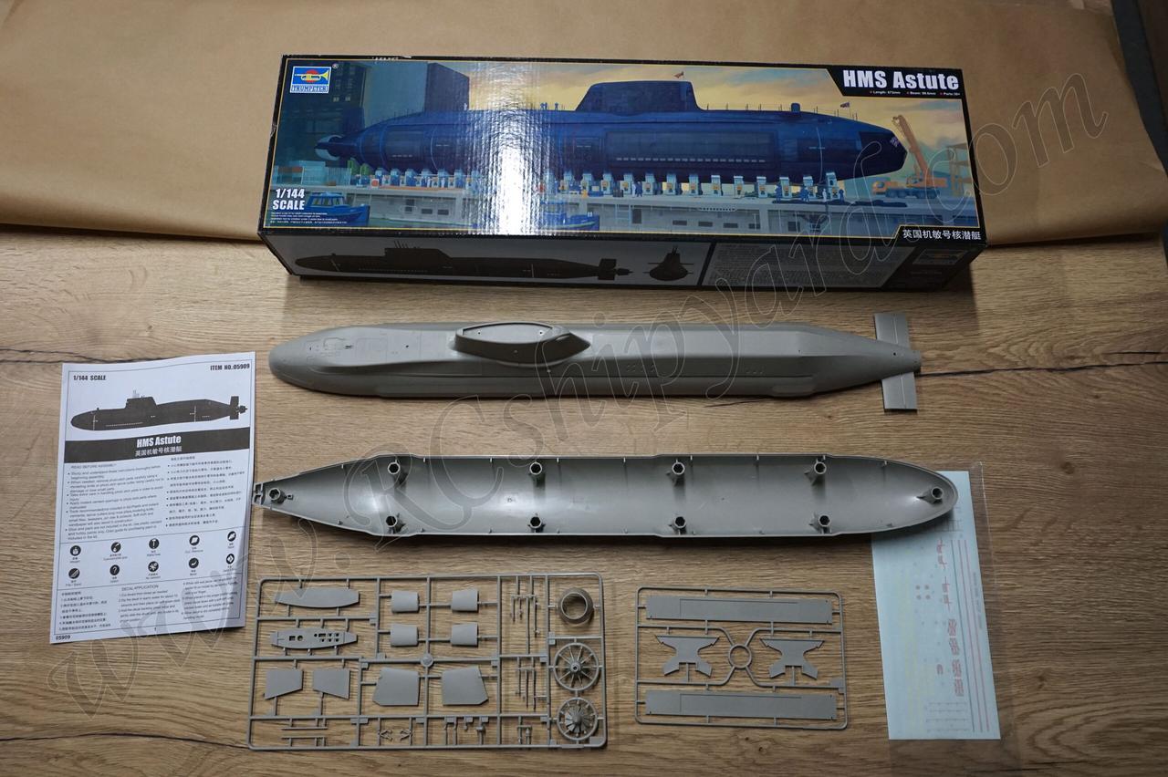
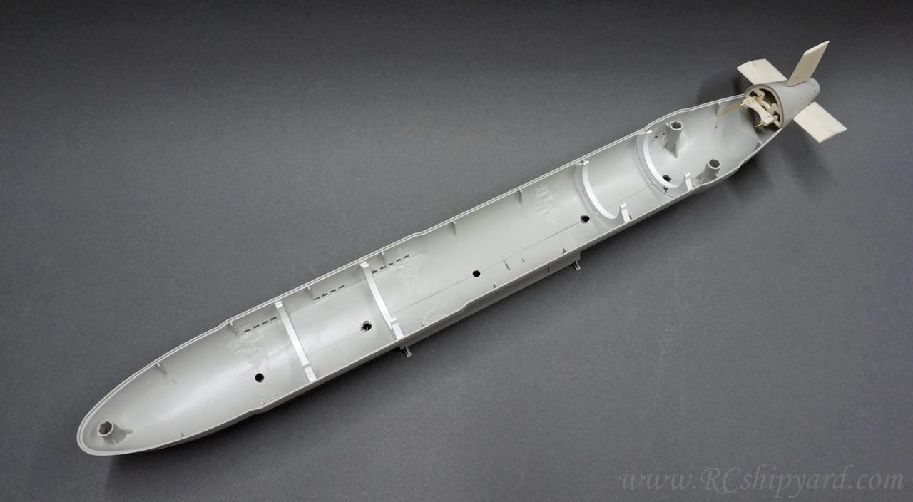
Box content of the Trumpeter Astute Plastic display model:
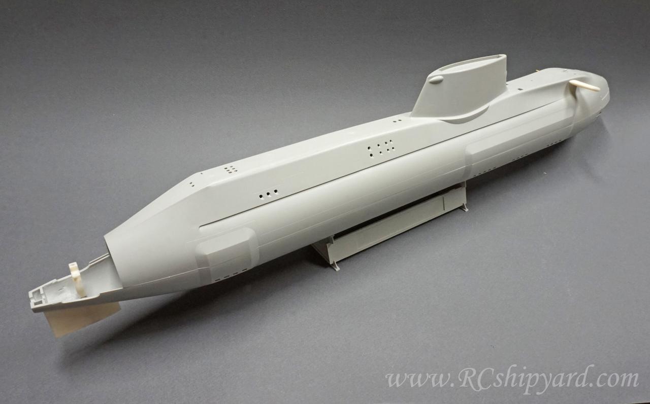
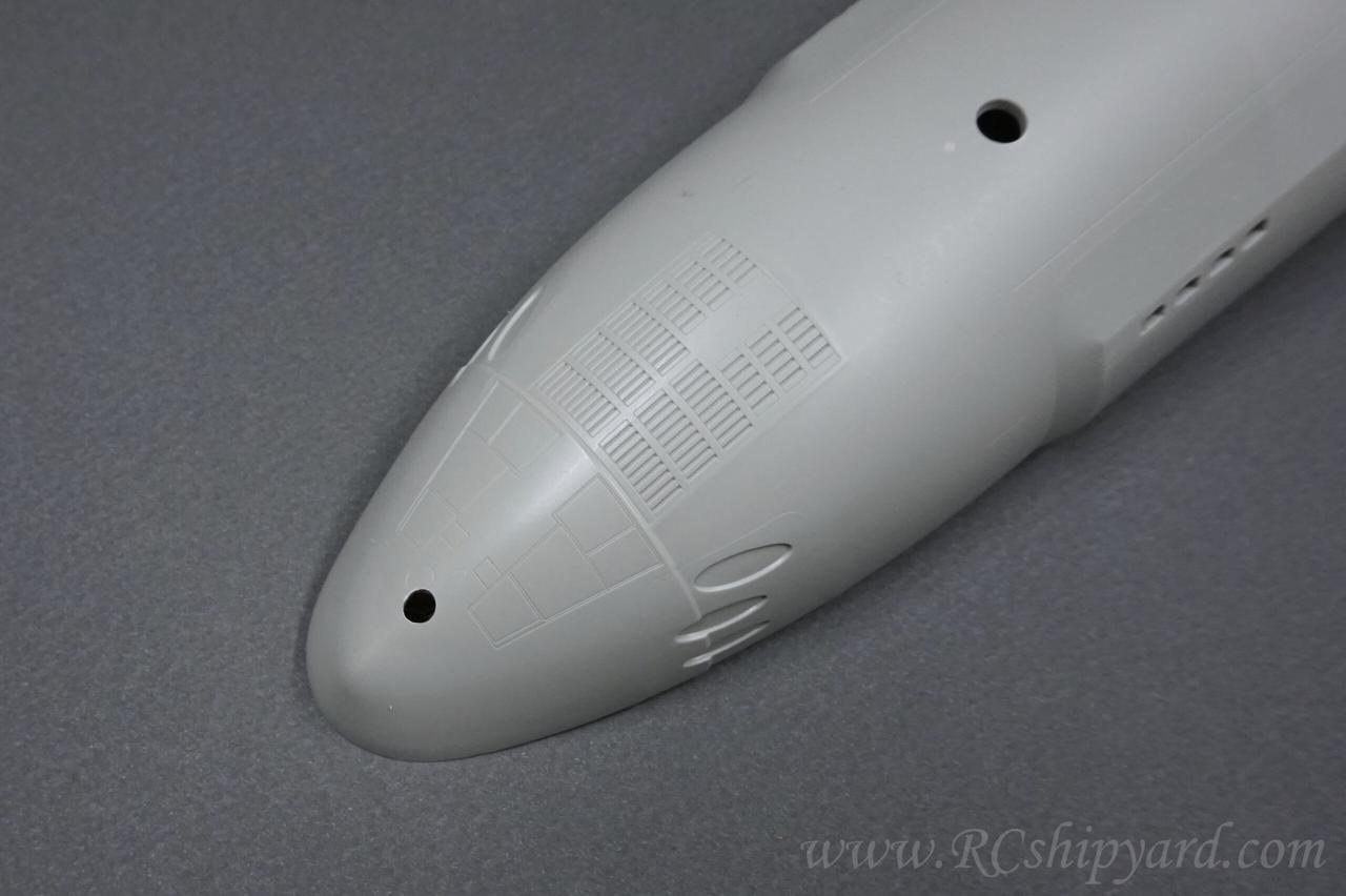
As always when it comes to plastic displays models of modern submarines the box content very modest. We get the hull split into two parts (upper and lower) and two frames of elements, where one of these frames is only the boat stand. Very, very modest content even for a modern sub. The hull lacks many details and looks a lot more poorer than for example the Soryu model – which has lots of hull details – including the anti sonar square coating.
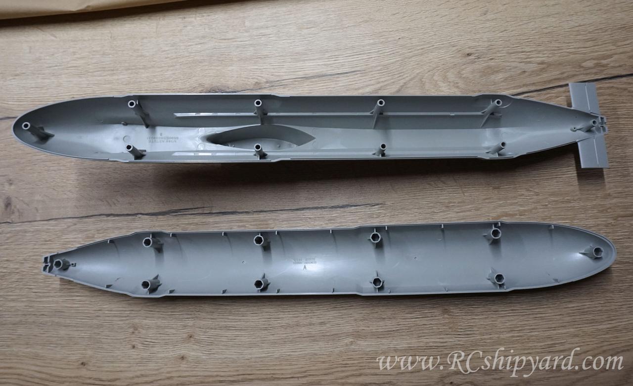
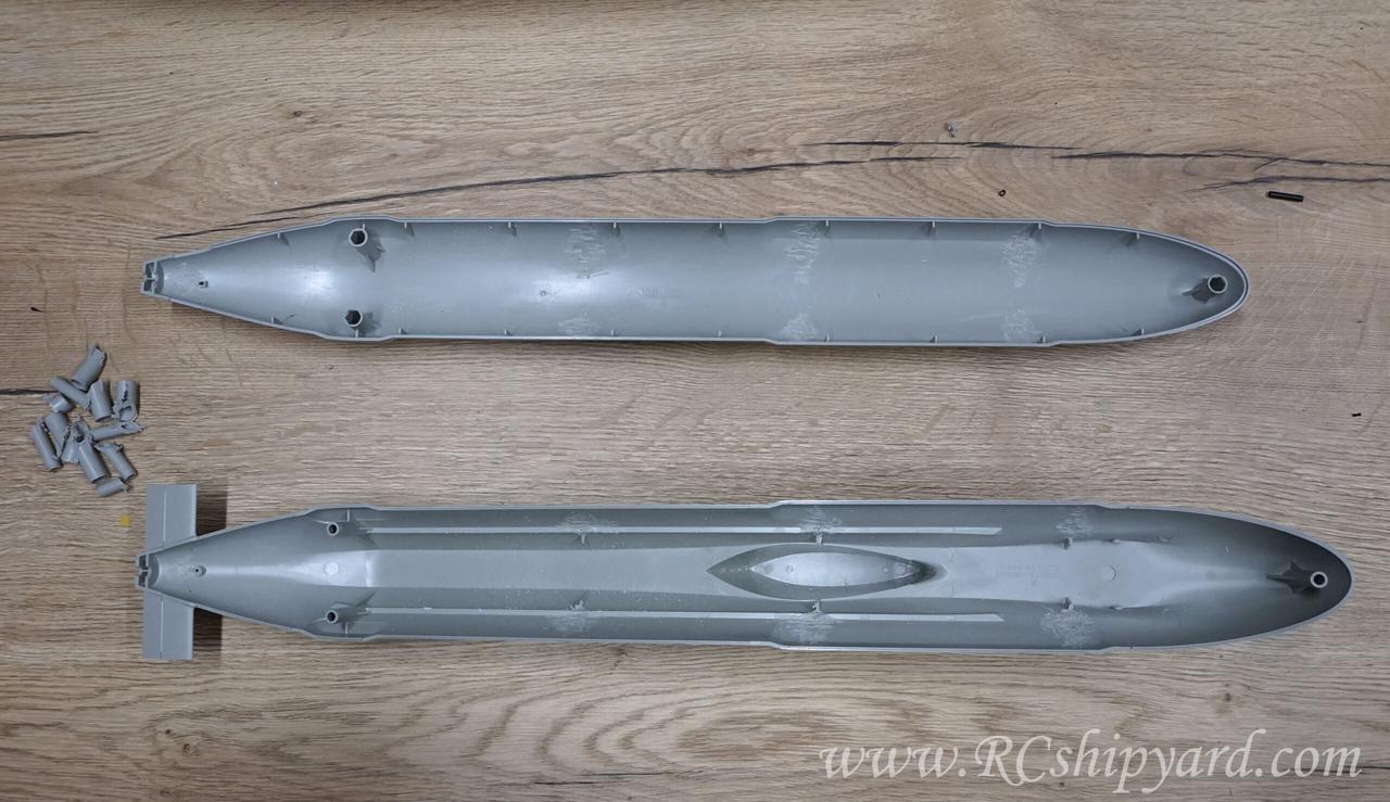
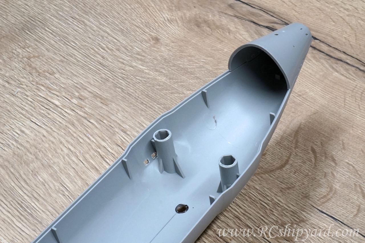
The hull itself is quite thick. It requires some work if we want to fit a 50mm (1,96inch) WTC inside. So first I had remove the 3 pairs of the middle pillars and the single one in the stern.
Removing the pillars was an easy job in general. I’ve used my trusty Proxxon mini cutter with a disc bit at first, then a bit with a pink sanding stone.
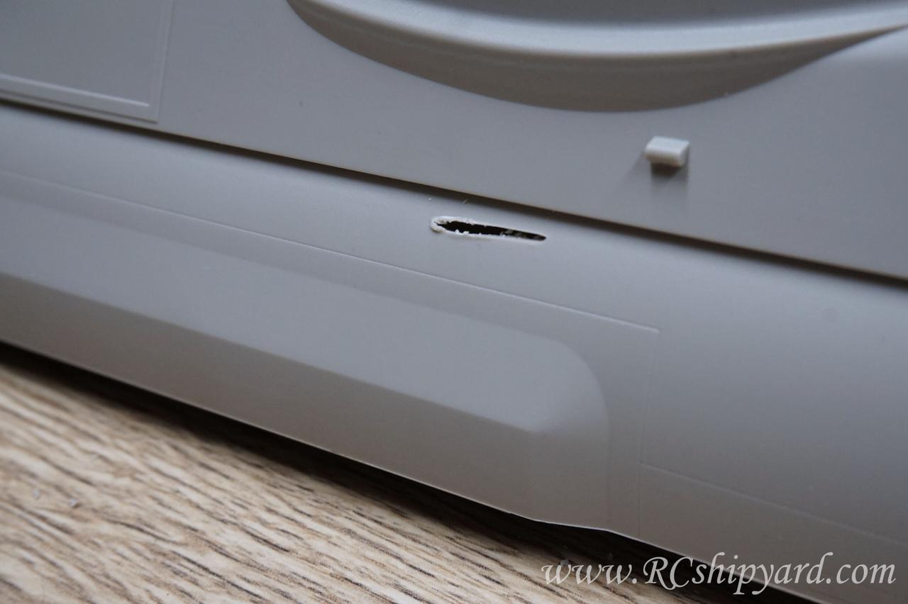
And to let everyone know, that even the best make mistakes – I did cut through the hull at one point. Not a big deal as it’s an easy thing to repair with Tamiya putty, but I should have been more careful when cutting out one of the pillars:
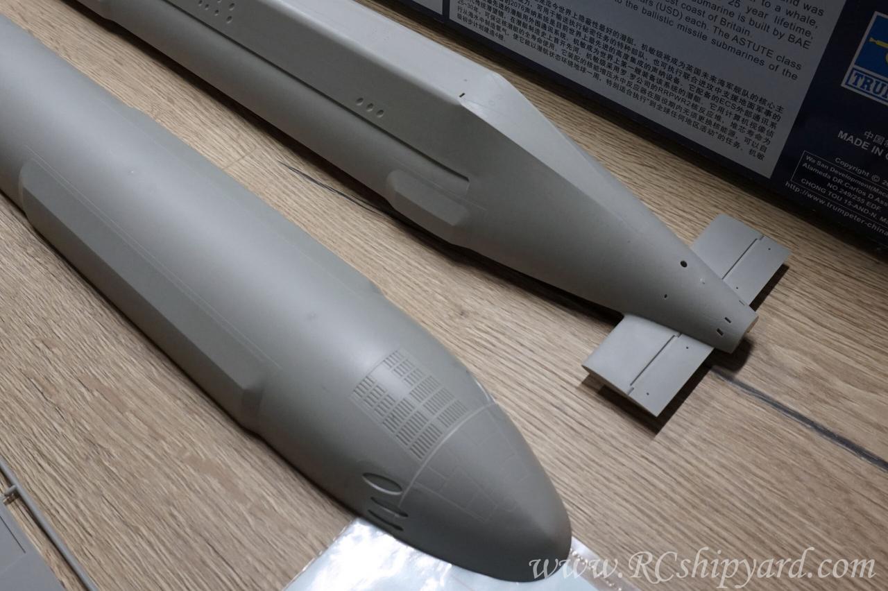
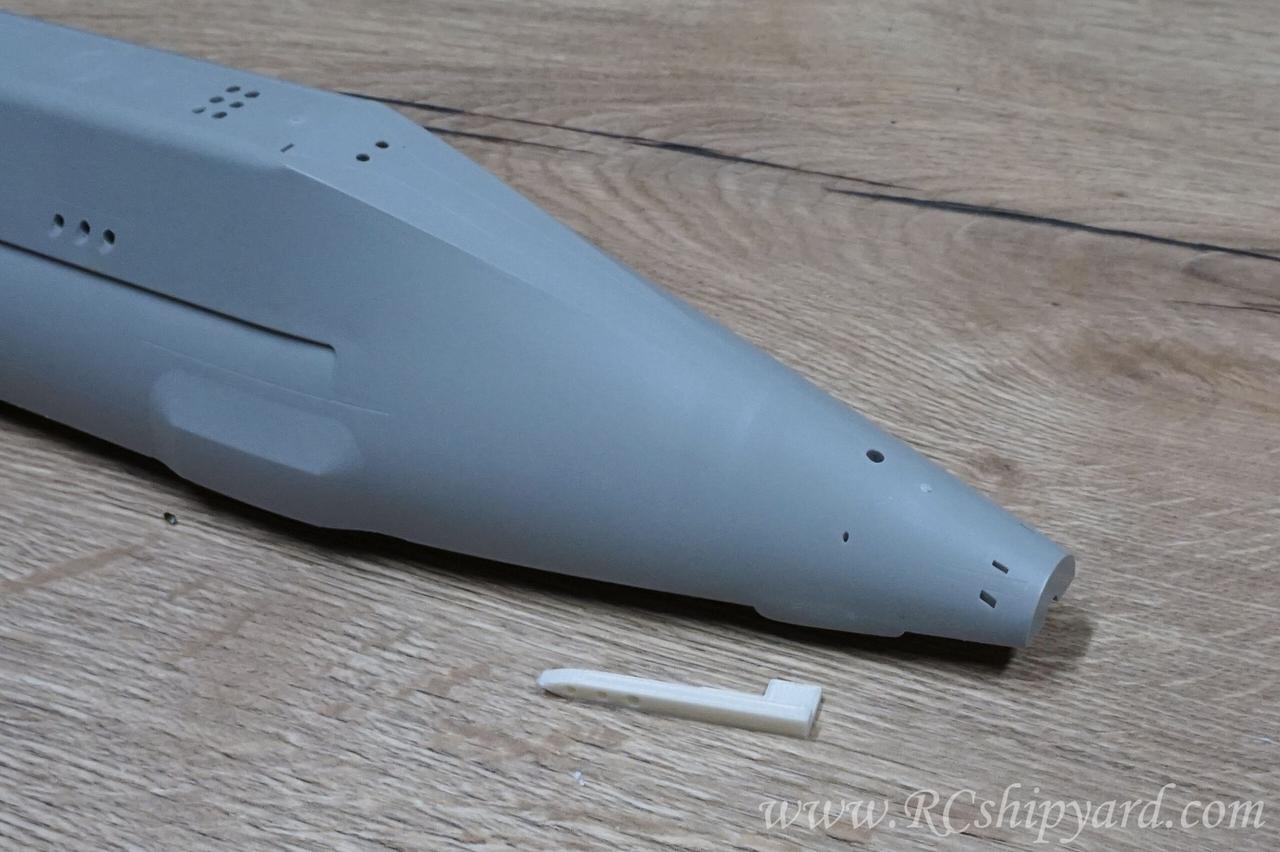
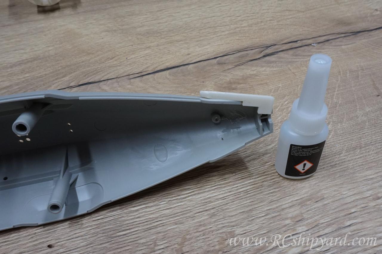
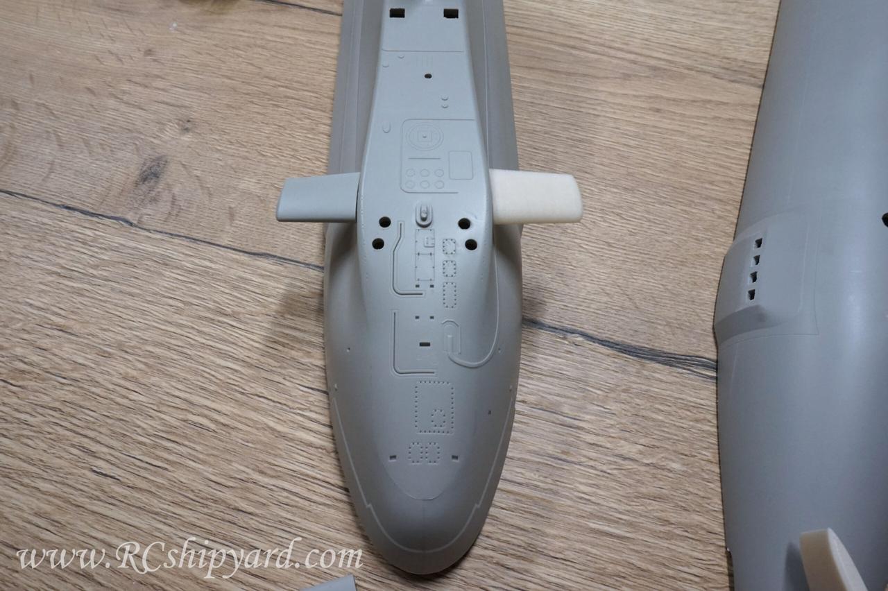
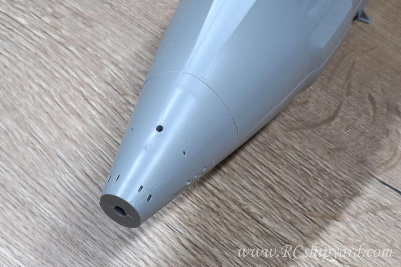
With the pillars gone the time came for the stern diving planes, which sadly are a solid part of the hull, so they’ll have to be removed:
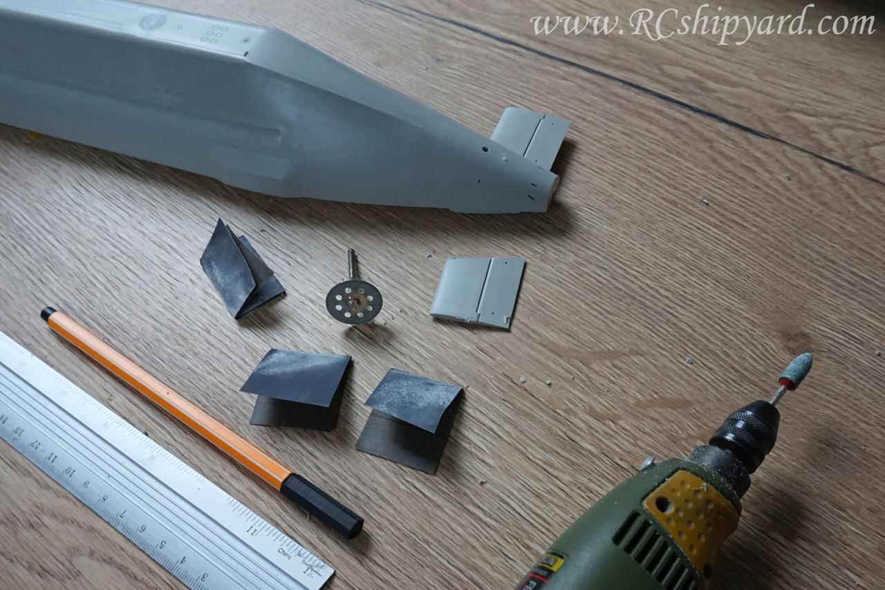
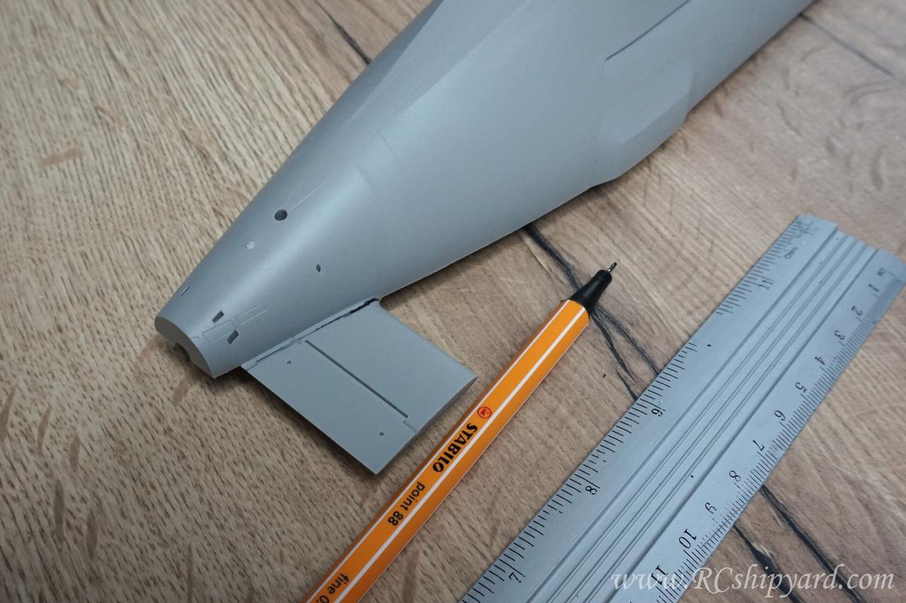
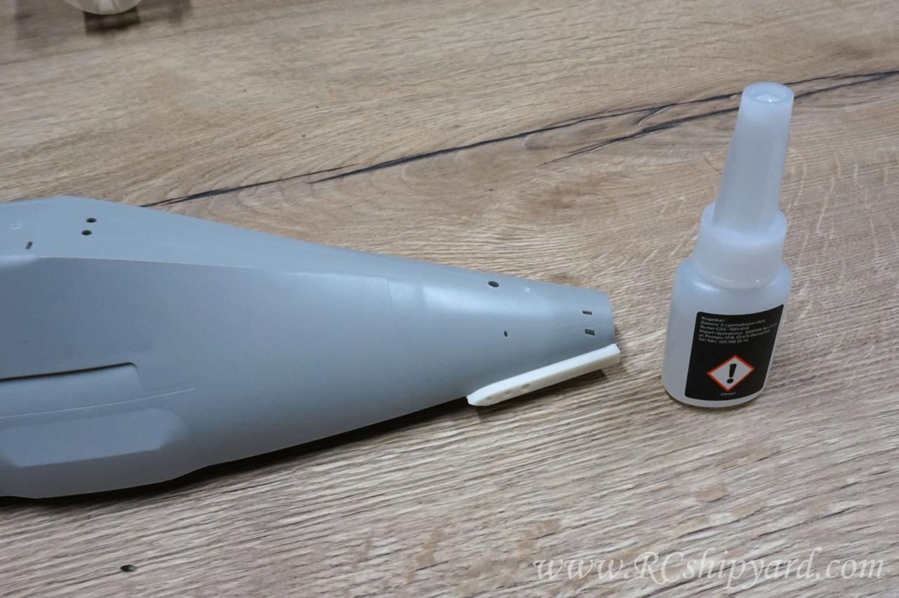
After successfully removing one of the stern diving planes, I thought that it might be a good idea to explain in detail how I do it. All the used tools on one picture:
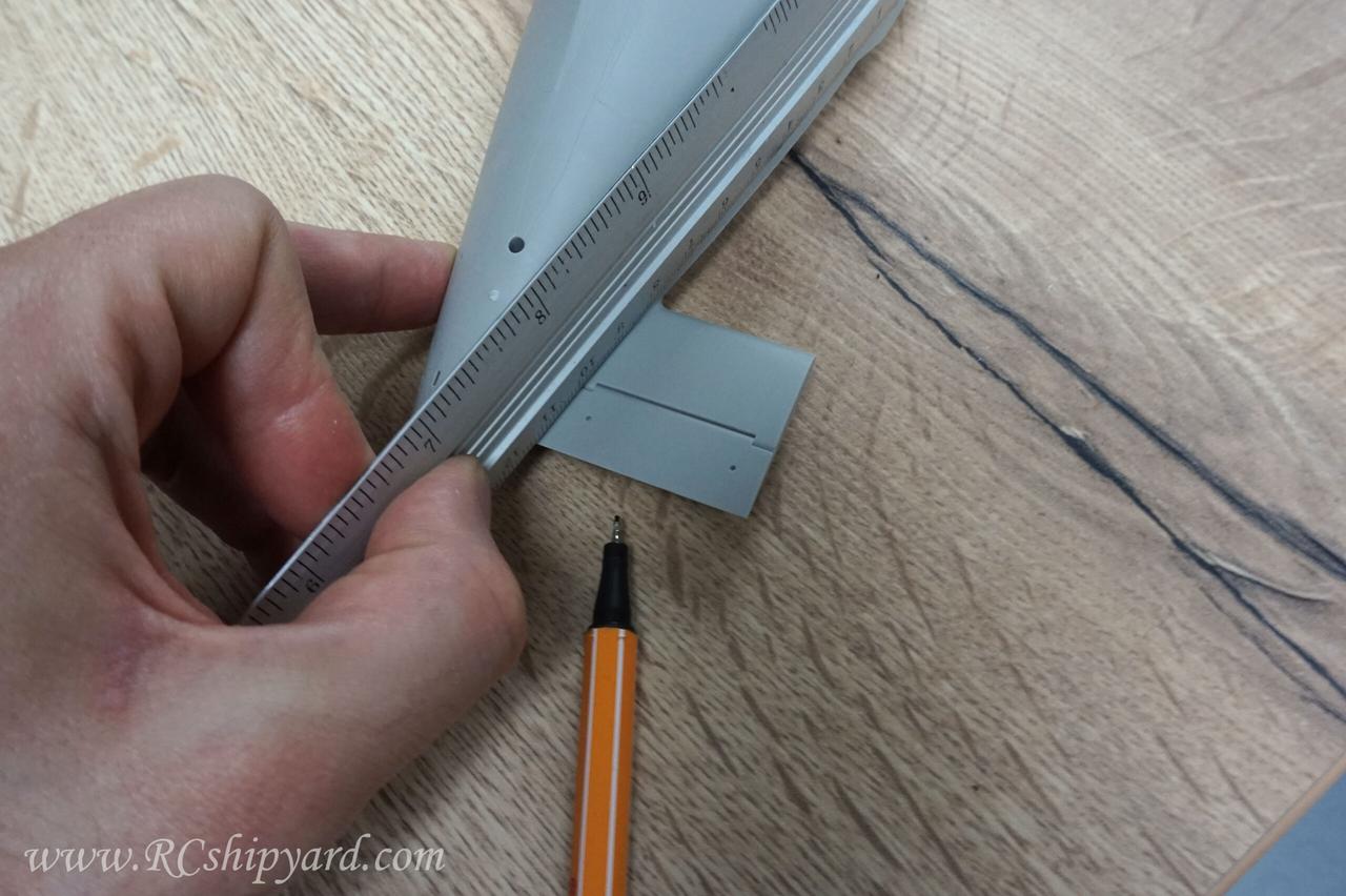
So at first, I like to mark myself the line of cut with some margin of space from the main hull. It’s because the cutting discs are fixed to the cutting bit with a screw and I don’t want that screw to scratch the hulls surface. I usually use a simple ruler for that.
I end up with an straight line which differs in thickness, but that really doesn’t matter, as the cutting disc itself is thicker than the line.
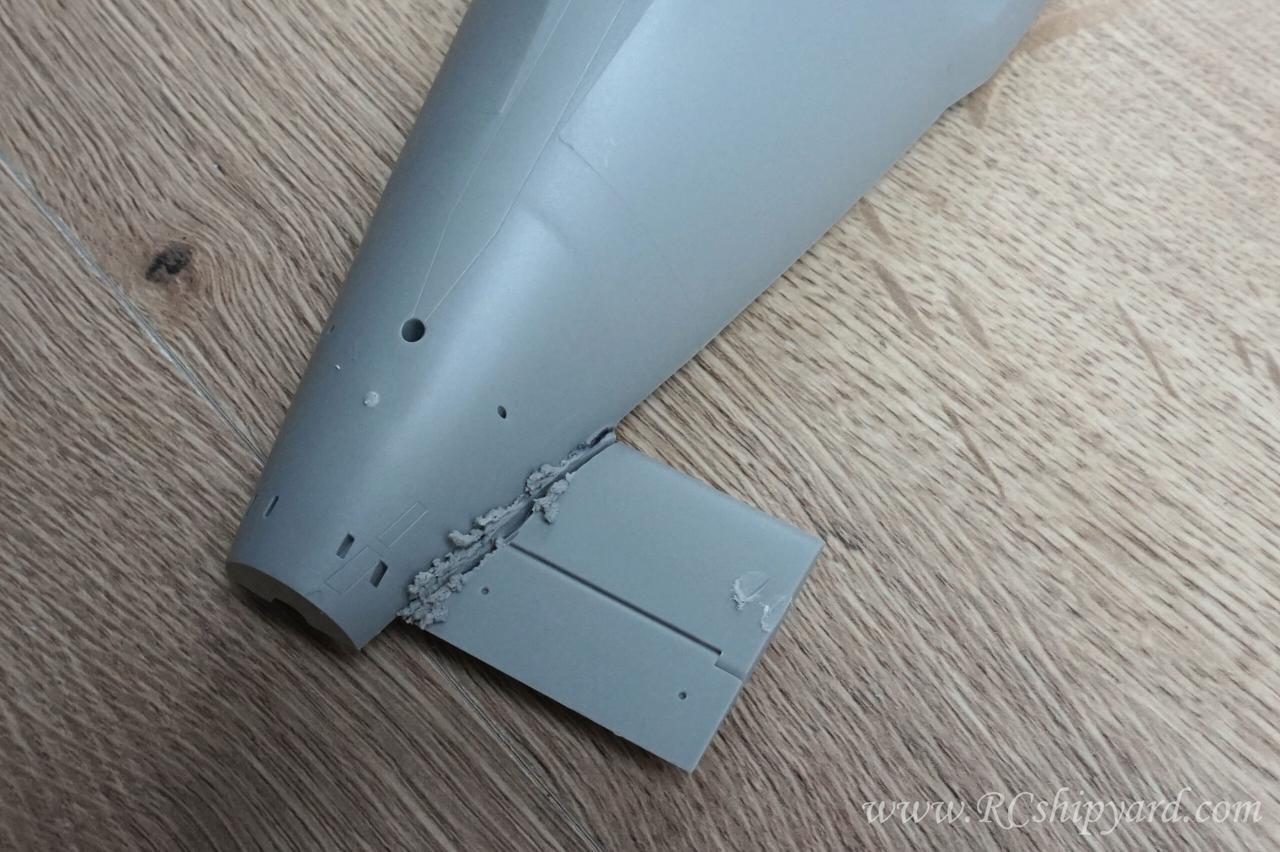
The first cut looks rough and has to look like this as the plastic melts from a high speed Proxxon cut – even at it’s lowest speed setting of 4000 RPM. However because of the margin of space between the hull and the line of cut, the melted plastic has lot’s space to cool down without damaging the hull:
After removing the melted plastic with bare hands, as it simply cracks off and some sanding – I end up with a very nice surface finish.
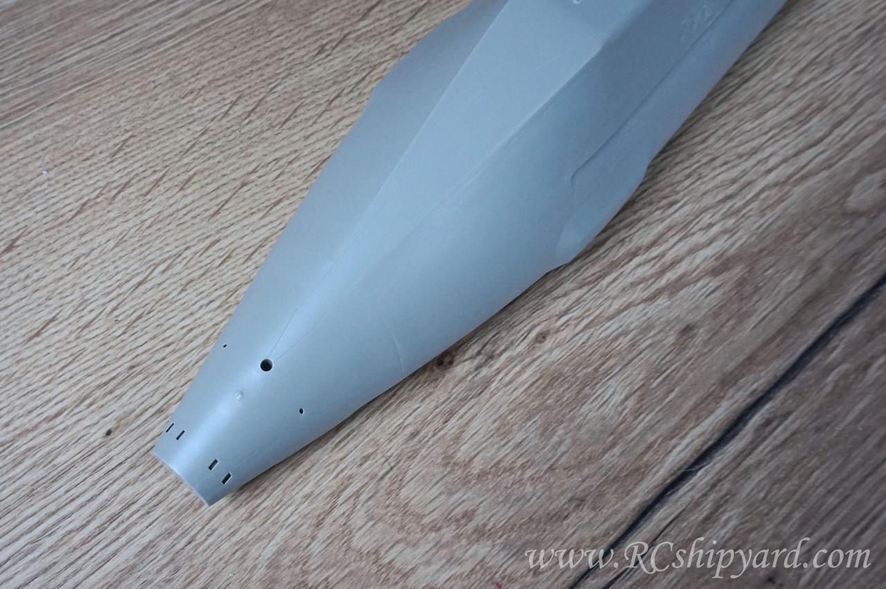
Hard to believe there were any diving planes there in the first place, right?
So the next natural step was to develop a new set of dive planes and slightly large rudders – especially the bottom one for better manoeuvrability during surface runs. The trick with the dive plane was that I wanted them split – like my design in the Trumpeter Seawolf conversion. The shape of the dive planes is identical as the original ones, but I did change their proportions – the control surface has been enlarged while the non movable part of the dive plane has been shrunken. I did develop the new set of bow planes too, as the original ones are in my opinion to fragile to convert them for operational ones.
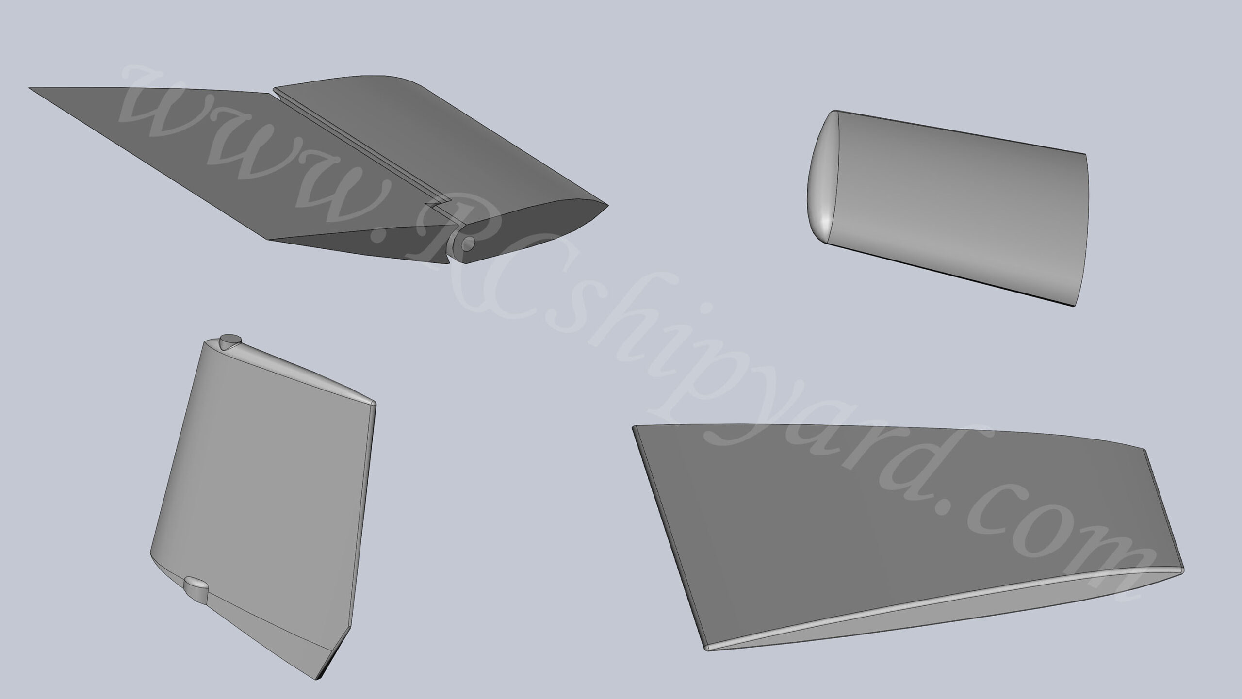
The designed planes and rudders have been 3d printed of course. They do fit the hull nicely. Installing the lower and upper rudder will be fairly easy as there are holes already in the hull for them already – so I have just glued in some brass bearings in them and the slide the rudders shafts in. However there’s a different story with the new dive planes, as there are no mounting points for them in the hull. Something had to be done about that…
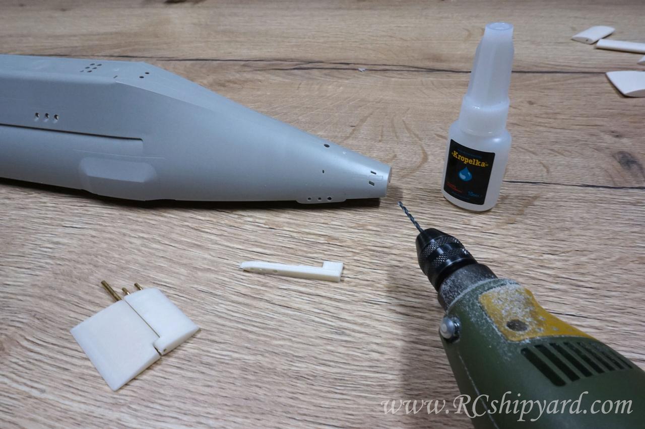
I wanted to make the process of installing the stern dive planes as easy as it could be – not only for myself, but also for others who will be willing to convert this model. So I’ve designed a left and right drilling template, which fits the hull of the Astute. The templates allow for a perfect alignment of both – left and right plane with as little effort as possible.
The template can only fit in one way and needs to be glued in temporarily to the hull with a small drop of cyano. There will be no visible marks after the glue and breaking off the template after it’s been used, as the glue only has contact with the surfaces which will be hidden in the further process of the model assembly: This means the side part of the hull, where the diving planes go…
…and the line of assembly of the two hull parts, which obviously will be covered by the lower half of the hull:
From this point it was just quick drilling without any worries.
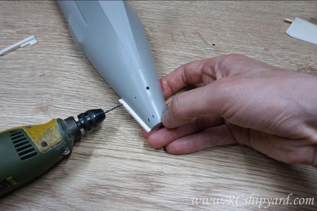
The idea is to end up with 3 holes – two securing the non movable part of the dive plane and the third one for the shaft of the control surface.
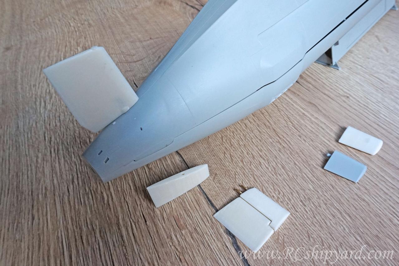
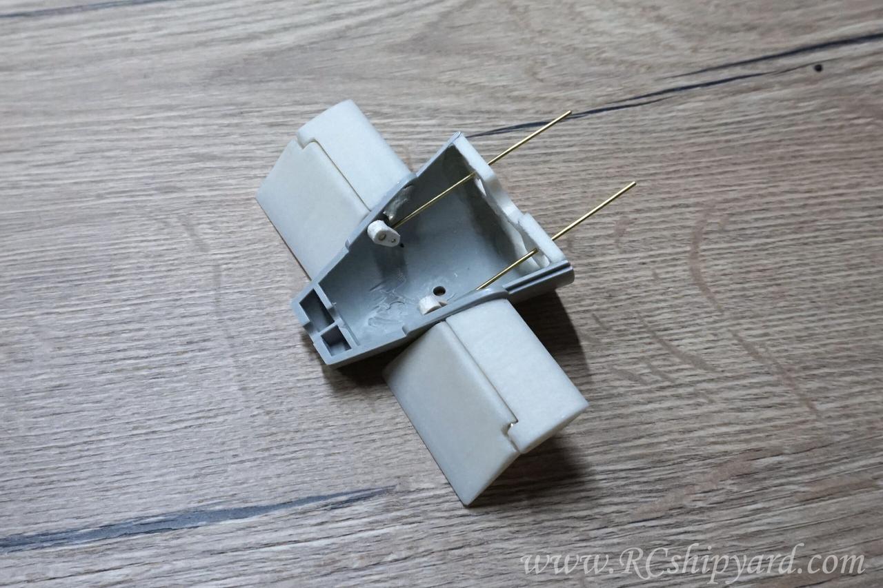
The new set of diving planers and rudders installed and the old plastic ones laying on the workbench for comparison. The fit is good and the fix feels solid.
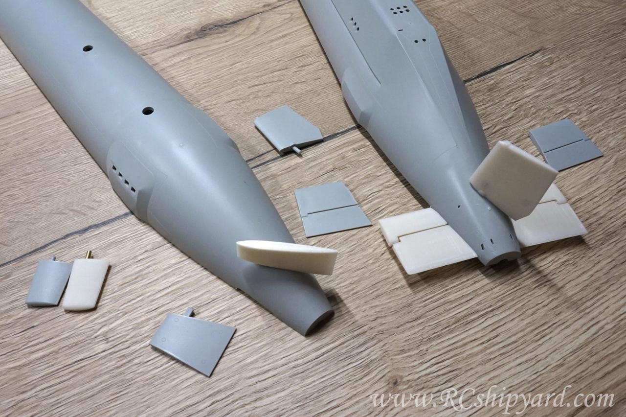
And of course the bow planes comparison:
As this KIT is intended for sale in the future, I want to design it as easy for assembly as it could be.
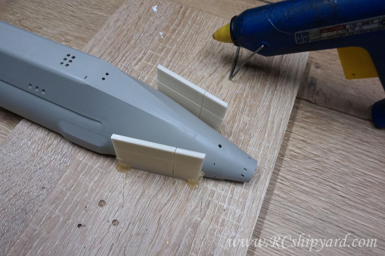
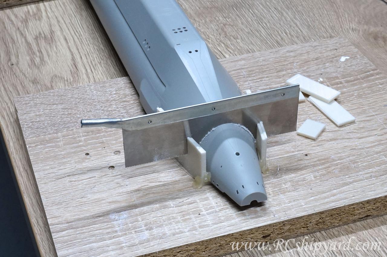
Cause of this, I have designed and printed out a a guide rail for a very thin saw (0.3mm – about 0.013″). The guide rail has been designed to fit the Astute’s upper hull shape.
The plan is to achieve an easy access to the WTC and separating the hull piece with the stern dive planes/rudders from the rest of the upper hull will greatly help with that. The guide rail has been glued together with the hull and firmly in place with hot glue. Hot glue is great when you need to glue something temporary as with smooth surfaces it doesn’t leave any marks after removal.
The slot for the saw is only 0.38mm – about 0.015″ thick and that allows for a very steady cut, but even as the saw is quite a deep…
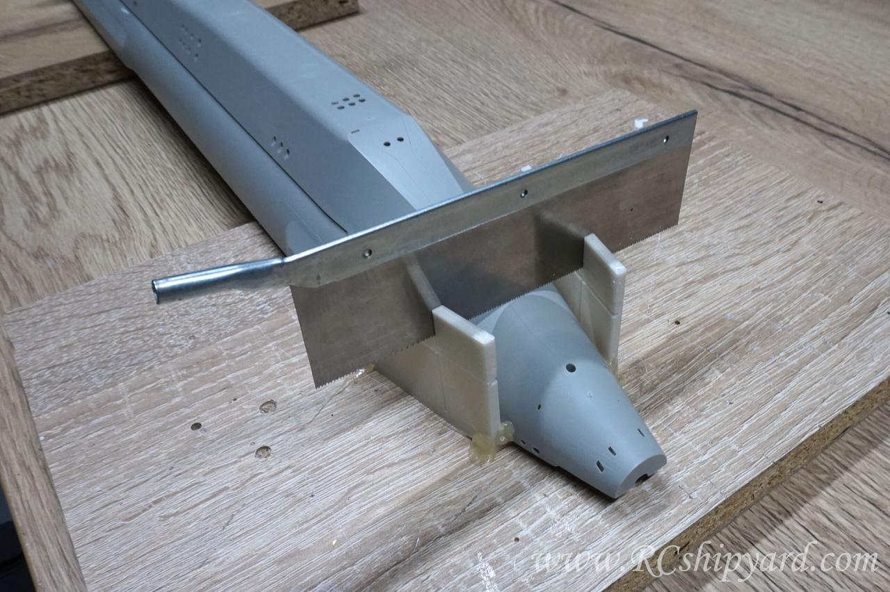
…sadly the cutting depth of the saw is not enough to get the job done in one cut.
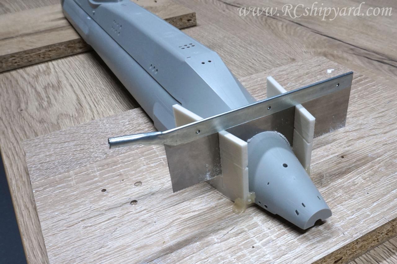
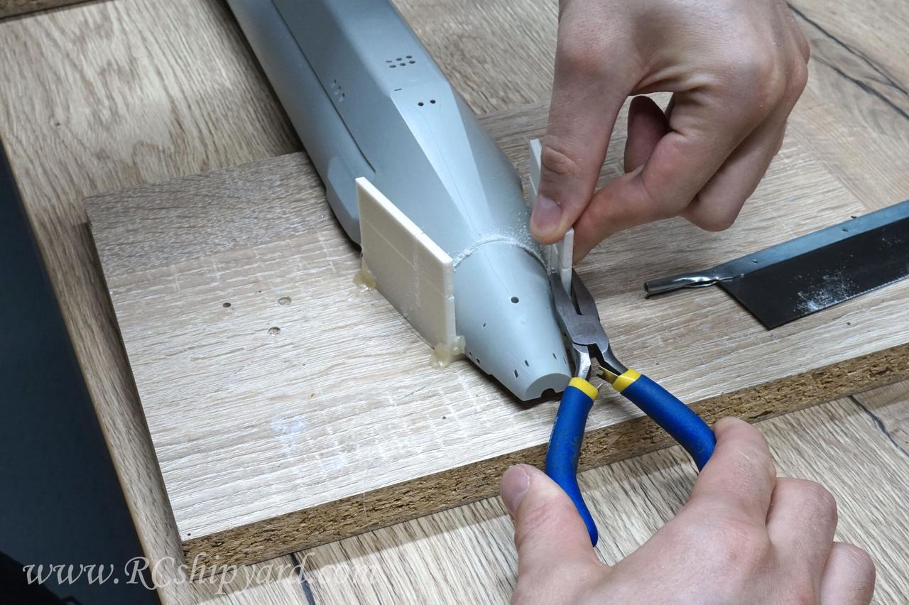
So the guide rail was designed in such a way that when you reach the limit of the saw you can break off it’s top parts. The lower parts of the rail should be grabbed with flat pliers to secure them from accidental breaking off, but after that it’s just simple to grab each upper piece with ones fingers to break them off.
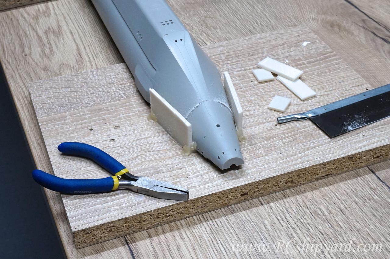
Now the guide rail is much shorter and allows to finish the job with the saw.
And what’s important the saw goes exactly in the same space.
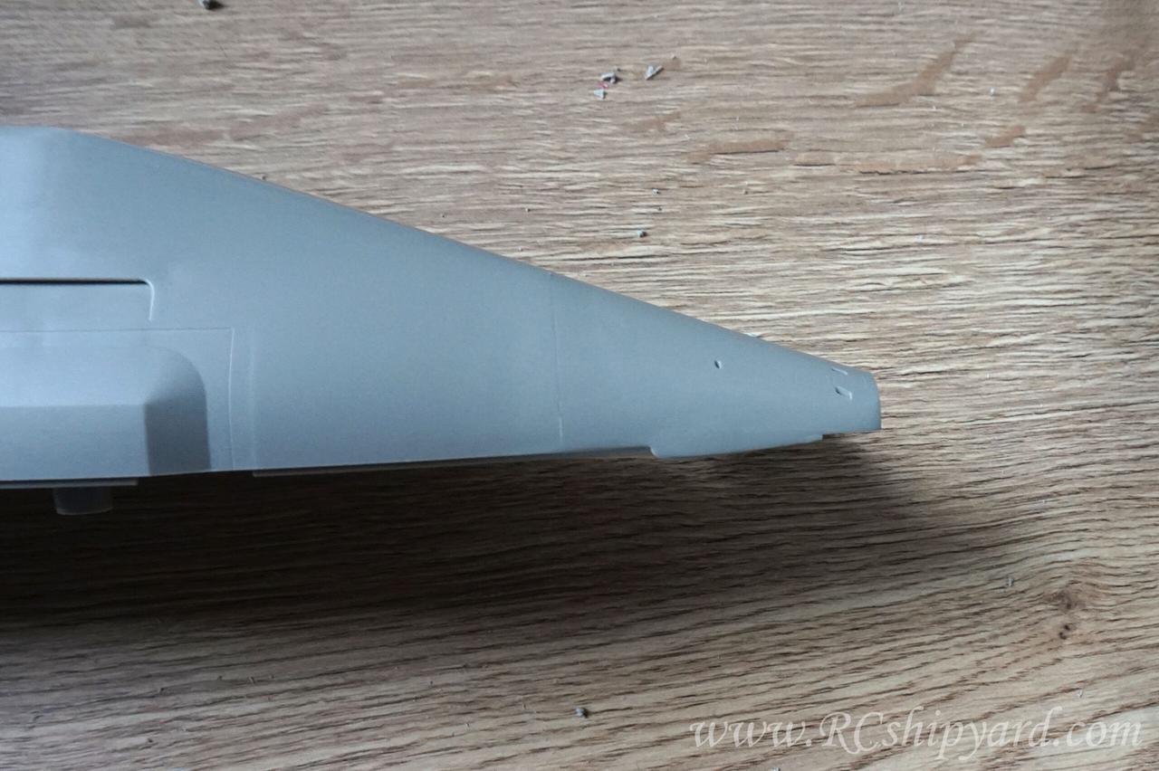
That allowed me to achieve a clean and straight surface of the cut
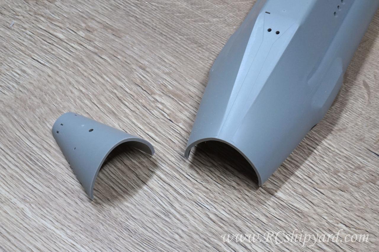
The line of cut is barely visible now and I’m pretty sure it won’t be visible at all when painted black.
Looks good.I’m happy with the result, especially as it’s easily repeatable for others.
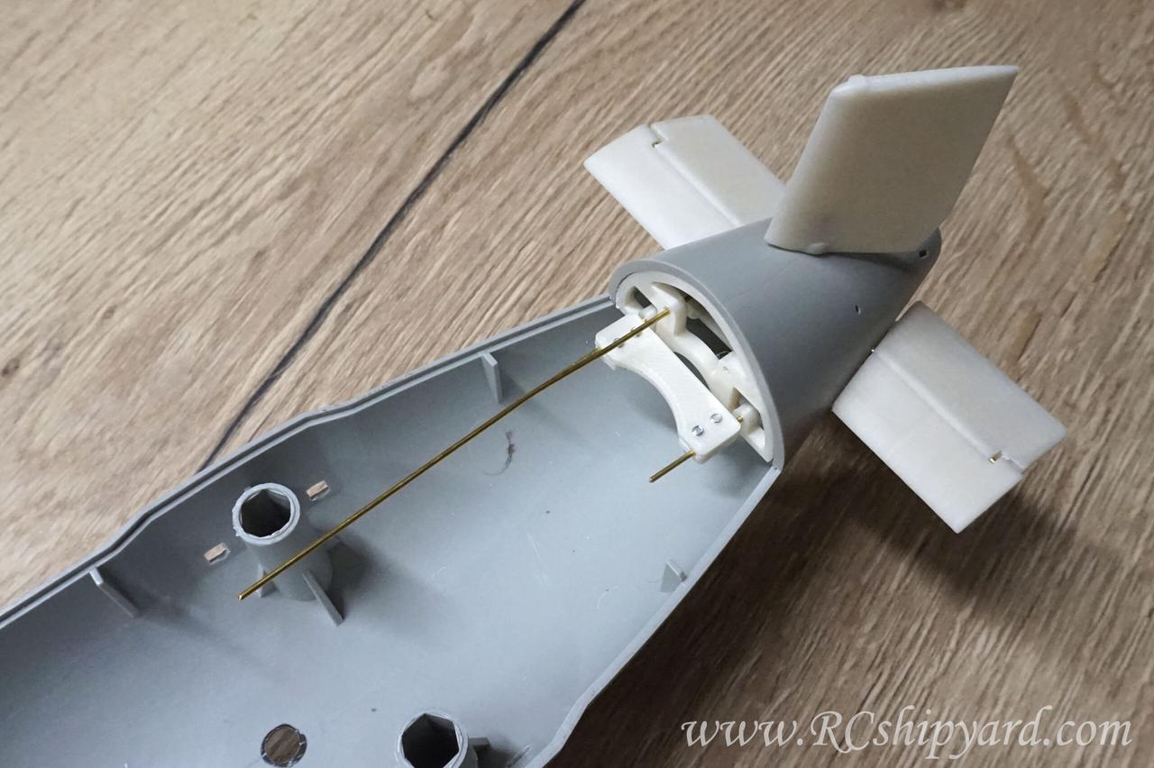
Further work with the stern dive planes and rudders setup.
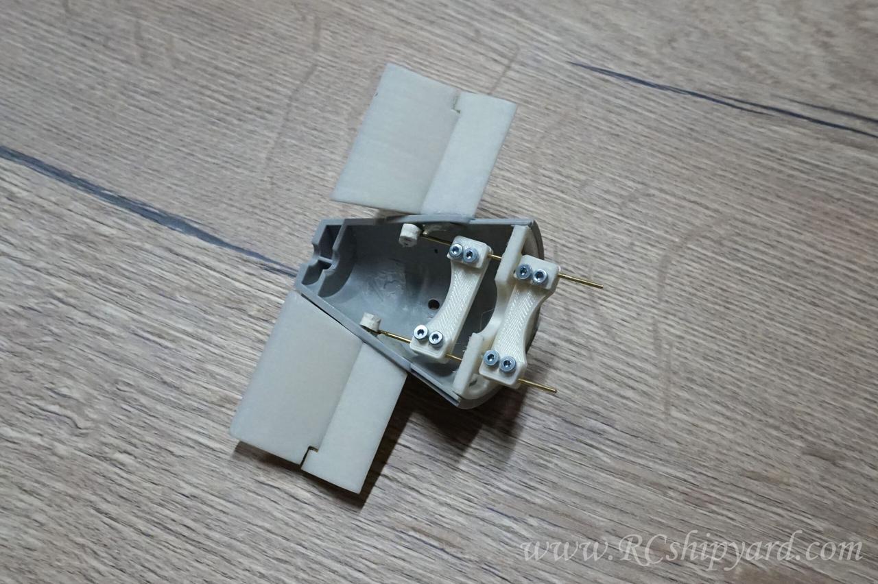
And a classic solution for the lower ruder – a 3 mm shaft will go through the center of the eye:
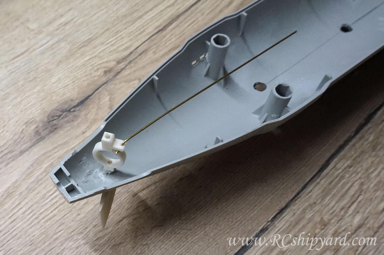
Last fit before gluing it all together, or at least that’s what I was planning before noticing something…
I did work on the pushrod for the bow dive planes too. The bow planes planes will be operated by the same servo as the stern planes. Of course the length of the model allows for a longer WTC with additional front servo for bow planes only, but I with a model of this size one good quality servo is enough. Plus I love it when my solutions are universal – like switching the WTCs between the models without the need of trim a change.
And the thing which I noticed earlier which made postpone the gluing of the stern dive planes/rudders together, was this enormous gap!
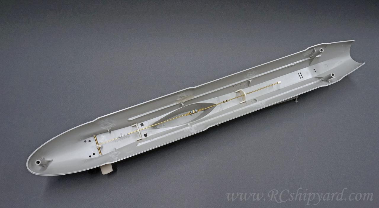
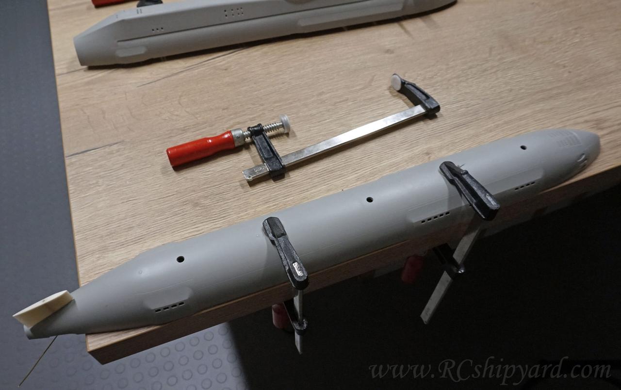
It was rather easy to determine which of the hull parts is twisted – In my case it’s the lower part was shaped like a banana. If you want to check your own hull with a line of cut such a this Trumpeter model – simply place the hull part on a flat surface and observe where the biggest gap is.
My solution to this was to fit the lower hull with clamps to the flat surface and heat the hull up with a normal hairdryer. Not one of those industrial heaters used on construction sites, just a plain hairdryer. I did heat it up decently, then let it rest. I did repeat this cycle went for quite a few times. After that I left the hull fitted with clamps in place for 24hours.
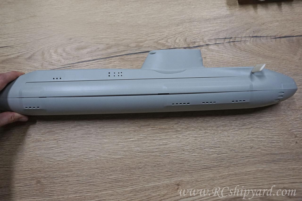
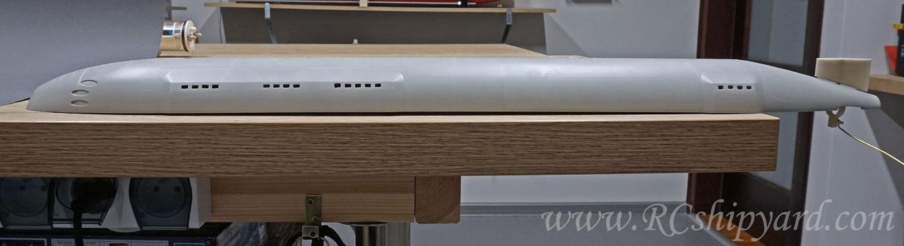
And the final result of the hull’s shape correction. It’s just the top part placed on the lower one – no screws, no force. I’m quite happy with the result. Nothing was burned or melted after all.
Cradle supports for my a 50mm cylinder. Designed and CNCed, happy with the results from the new cnc machine.
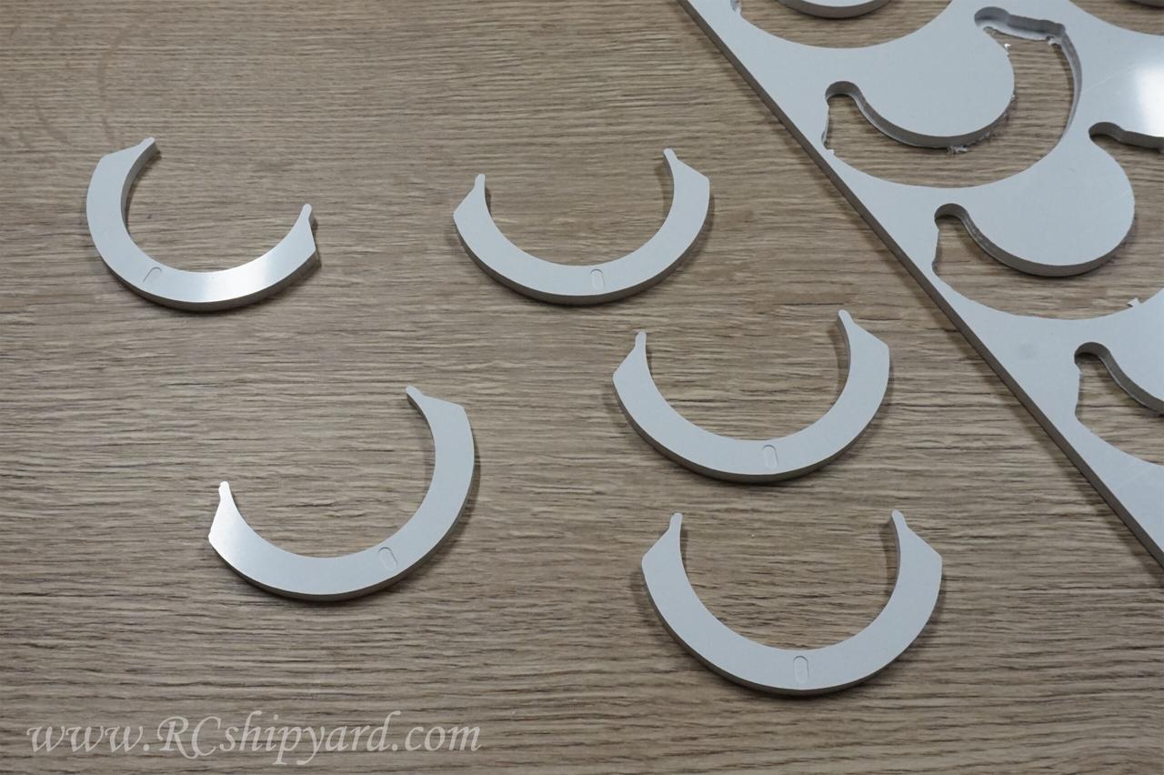
A bit later four of these have been glued in position. They come in two sizes as the Astute’s hull is wider at the bow.
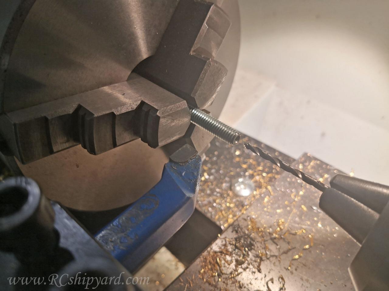
Now that part of this building long is a little unnecessary as you can simply buy stainless steel (or brass) inserts, but because I had none at the time, I decided to make my own. I’ve used a 6mm threaded rod, which I have drilled with a 2.5mm drill at first and tapped a M3 thread inside right after.
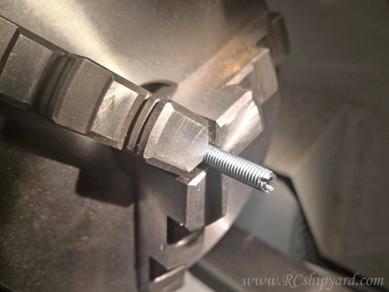
Then there was a need of cutting in a slot for the screw driver.
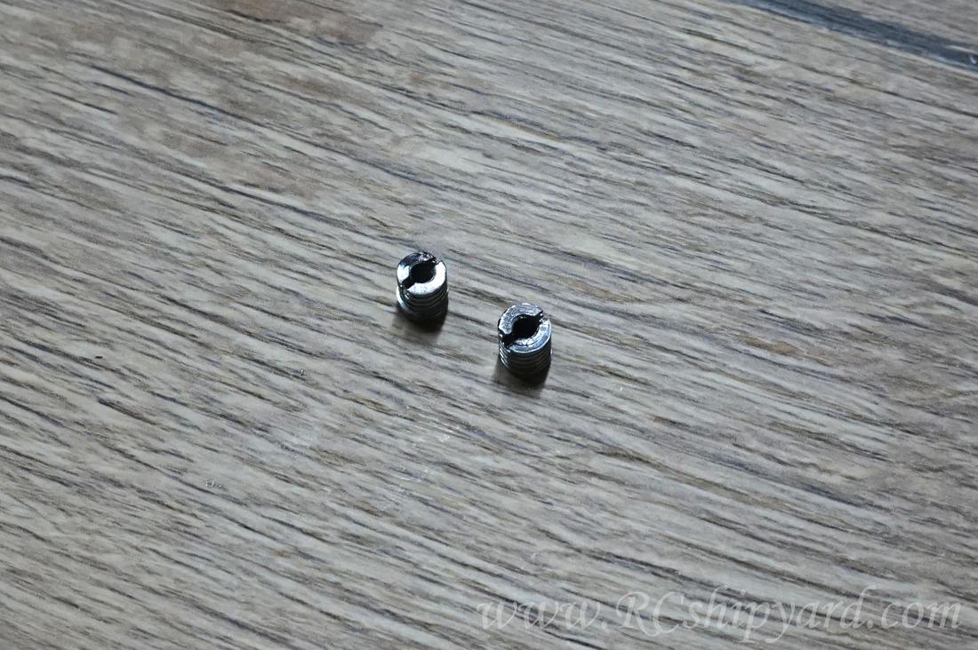
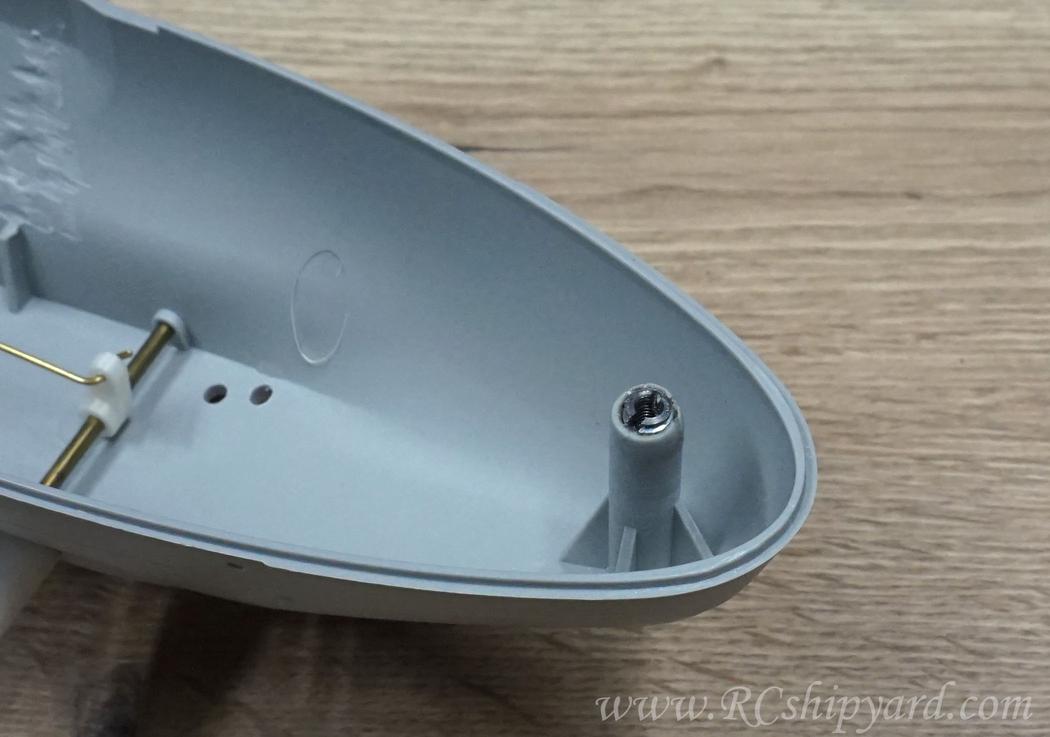
and quickly 3 stainless inserts were born (one of those was already in a model). They all will go into the remaining pylons in the upper part of the hull as a part of the hull locking mechanism.
And one of the inserts in it’s place:
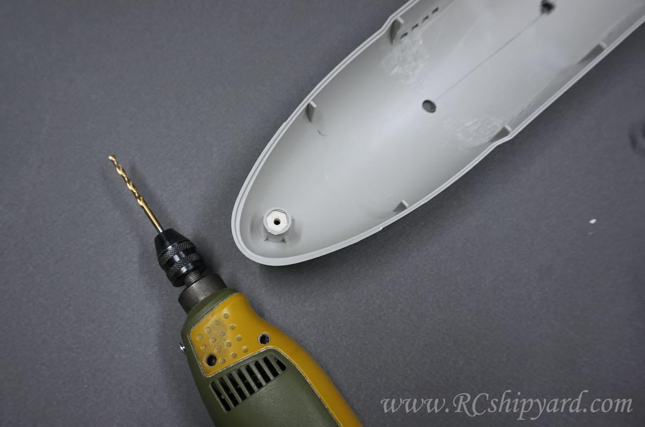
So the lower part of the hull requires drilling 3 holes for the three M3 screws (my M3 screws have a 6mm hex head). It’s very important to make the holes parallel to the pylons with the threaded inserts in the upper hull, so I decided to drill them in 3 steps. Each step with it’s own drill template. Template number one – 2mm
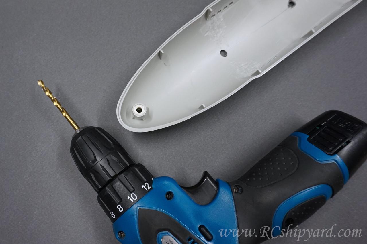
Template number two – 4mm
Template number three – 6mm
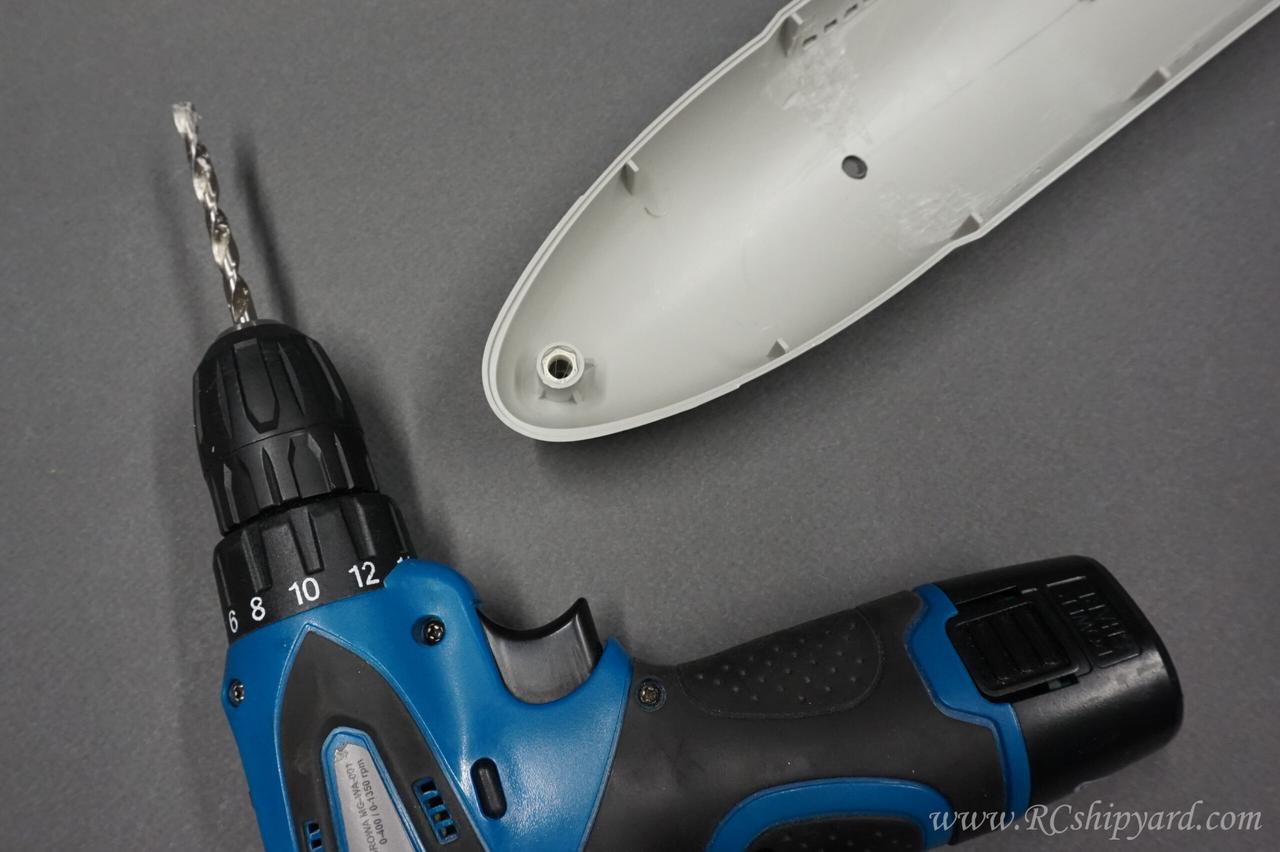
My other reason for dividing the drilling process into 3 steps was, that I really wanted a nice, clear edge of the screw holes in the lower hull.
More soon!