
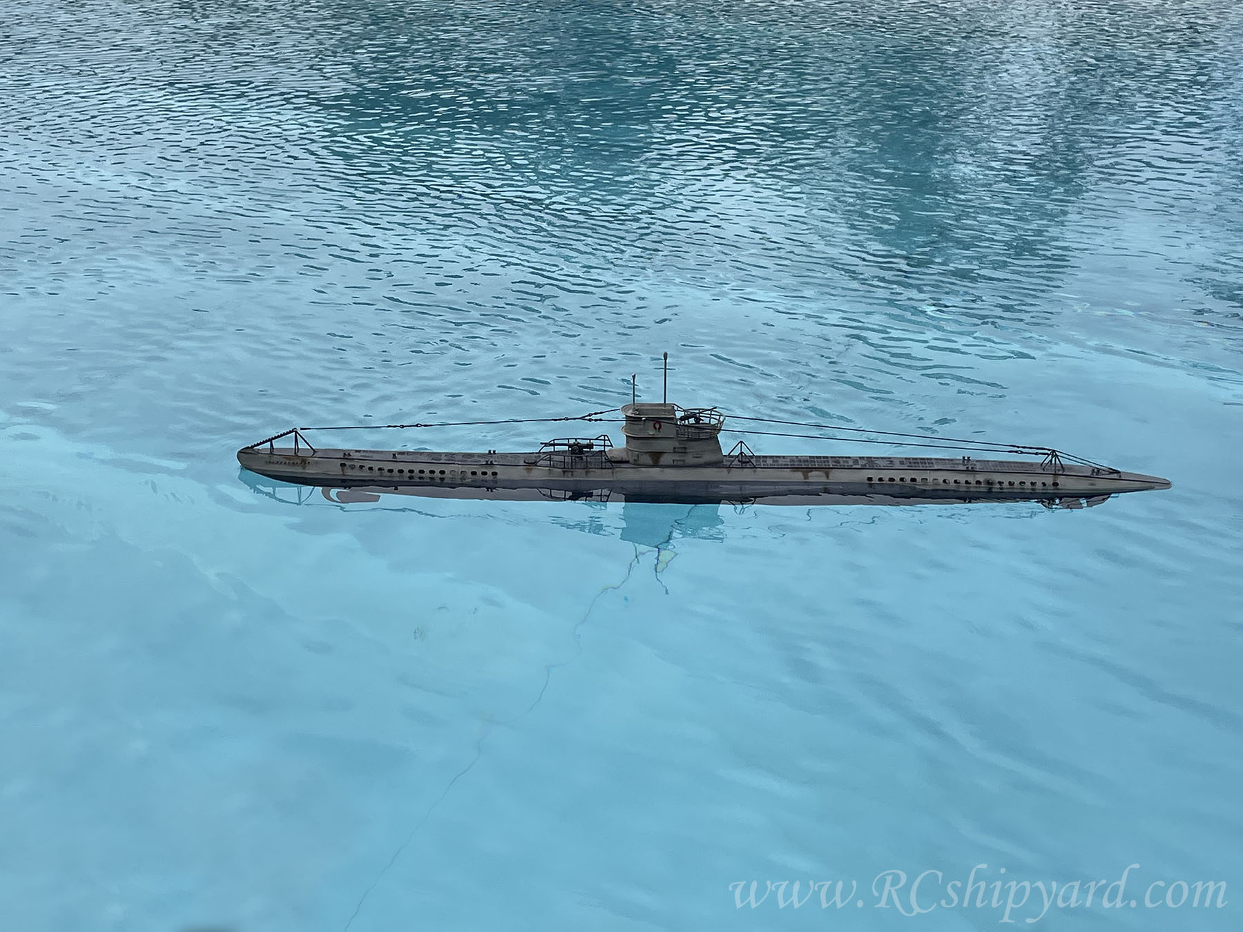
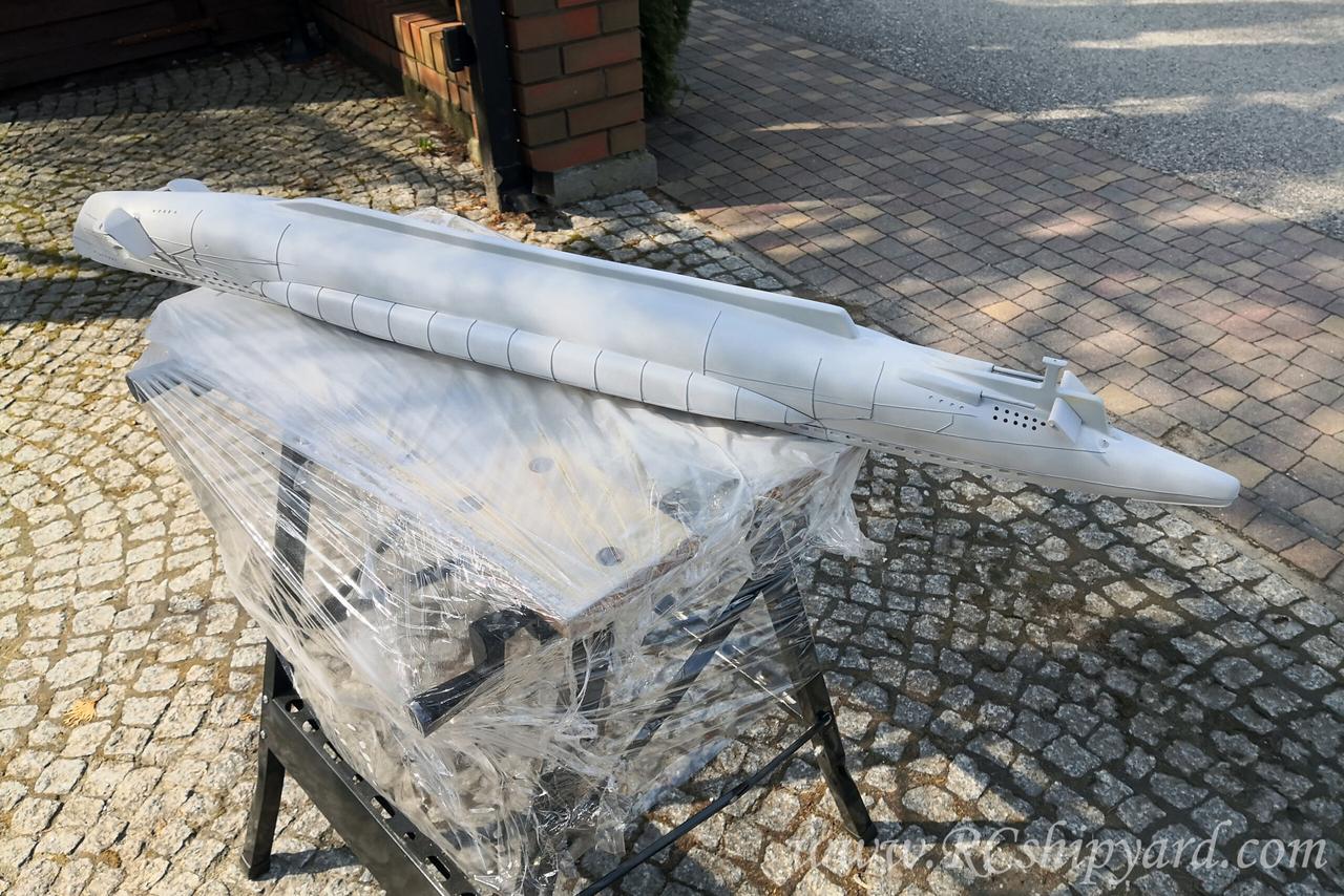
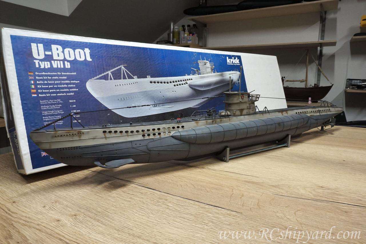
Uboot Type VIIB (Krick)
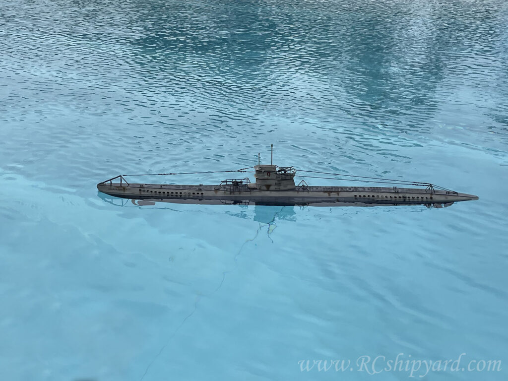 U99 – Otto Kretschmer’s boat
(A Very modified set from Krick, not much of an original Krick left)
Measurements:
- Length: 112 cm
- Displacement:
- Scale: 1:60
- Type: static diver (vented ballast tank)
I bought it only because it was cheap and I was so curious how bad it is. Well… It’s a terrible set which I have transformed into something really great!
Built start: 18.05.2021
Maiden voyage: 18.09.2021 (Neulengbach submarine model makers meeting)
last update 13th October 2021
Table of contents:
1. What’s in the box?
2. The main hull elements:
3. Water Tight Container (WTC) – assembly part 1.
4. Rudders and stern dive planes – part 1.
5. Bow dive planes
6. The motor block.
7. WTC assembly – part 2.
8. Rudders and stern dive planes – part 2.
9. Decks
10. Conning tower
11. Hull details – part 1: welds
12. Painting – part 1: primer/undercoat
13. Painting – part 2: base colours.
14. Hull details – part 2: deck details.
15. Painting – part 3: Weathering
16. Hull details – part 3: lines and rudder stabilizer.
17. The hull has been finished!
18. Internal systems: RC, diving system, battery pack.
19. Ballast system in the VIIB – how it works.
20. Maiden voyage
21. Some final words and thoughts.
22. Repairs and modyfications after 2 years.
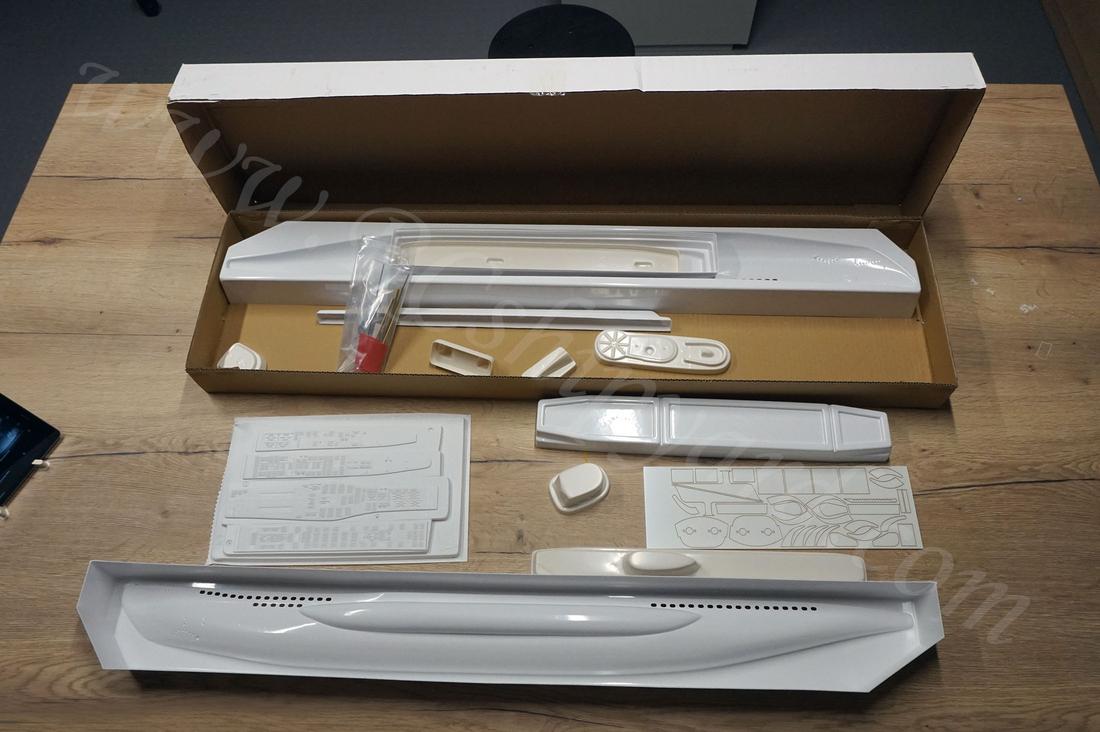
1. What’s in the box?
I bought myself the Krick VIIB kit as it was a dusty, cheap thing in my local store. My intention was to use it as a learning platform how to work with ABS based hulls, as in the future I would like to assemble something a bit more detailed and complicated, but still ABS based – like the Robbe’s Type XXI Uboot (as a static diver). Also, I have to finally learn myself some weathering as I have never done it before.
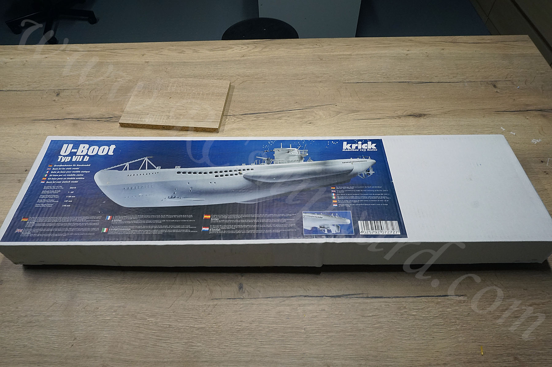
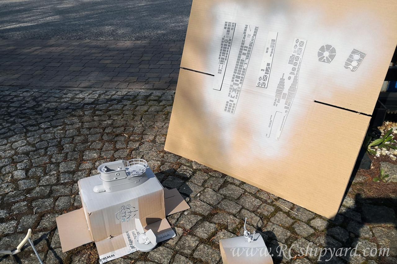
The content of this box is rather modest and makes me wonder was it even worth the cheap price, but no one should cry over a spilled milk:
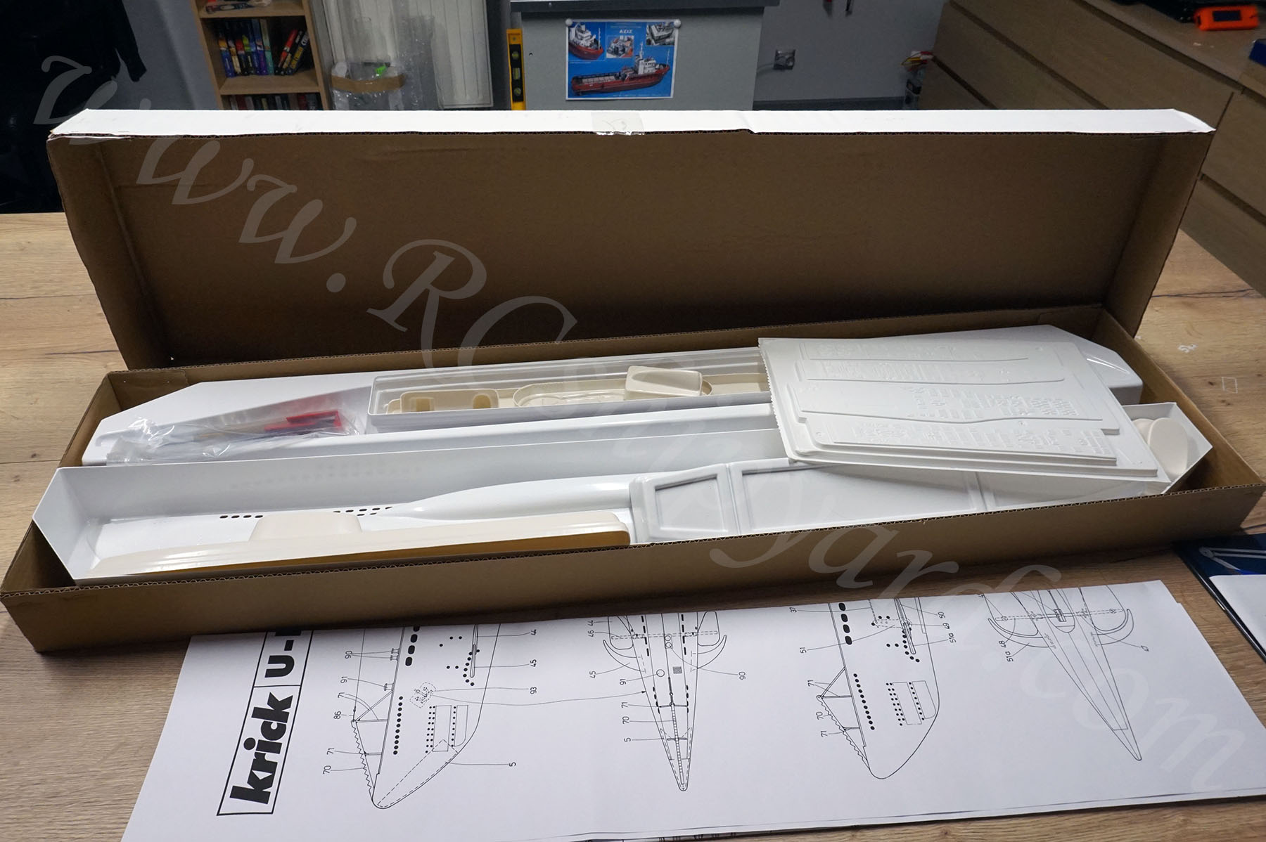
The KIT includes classic vacuum formed ABS parts with pre cut polystyrene sheets. There are some smaller parts like props and shaft, but… Oh boy! I’ll need to make lots of new elements! This thing can be actually a bigger challenge than the Engel sets!
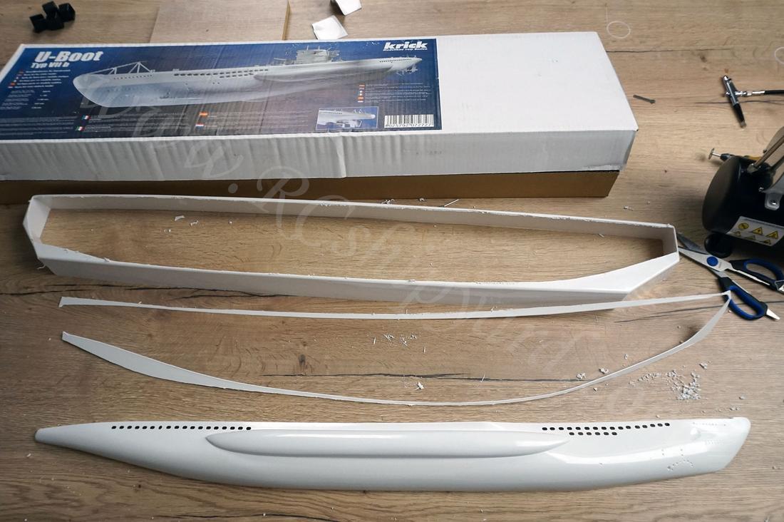
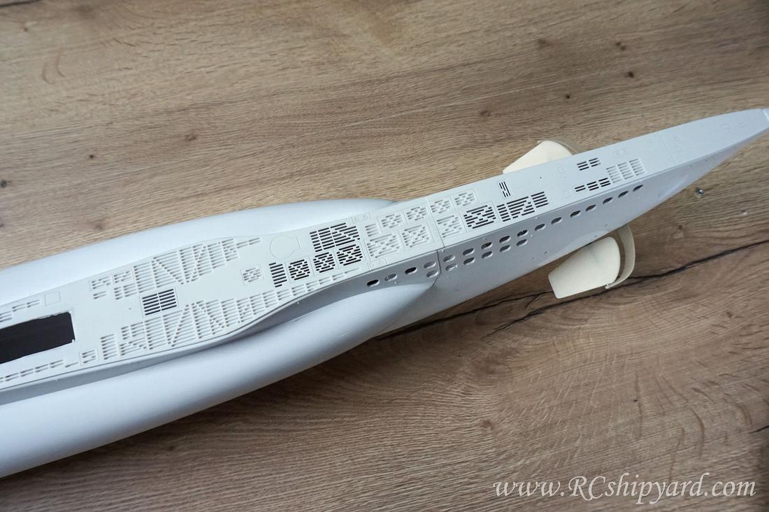
2. The main hull elements:
So it’s time to start. I’m planning to write this building log almost as a manual, as I think building threads help especially folks who enter the hobby. I hope that none of the more experienced model makers will feel offended by that. The hull is a thermoformed ABS. Cutting it out may be problematic, but only if you don’t know the “how to”.
To cut out the extensive material I simply use my Proxxon with occasional help of SHARP scissors.
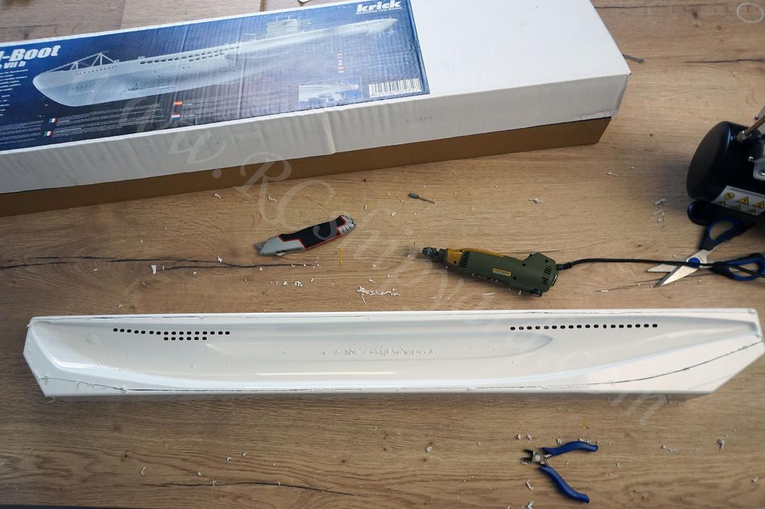
That first cut has to be done to allows us placing the parts flat on the workbench:
As it lays flat it’s easy to use the knife for the fine trim. The first “cut” is done without any pressure – only to scratch the surface. Adding a little force is required only in the 2nd or 3rd run. It’s absolutely not necessary to do a cut through.
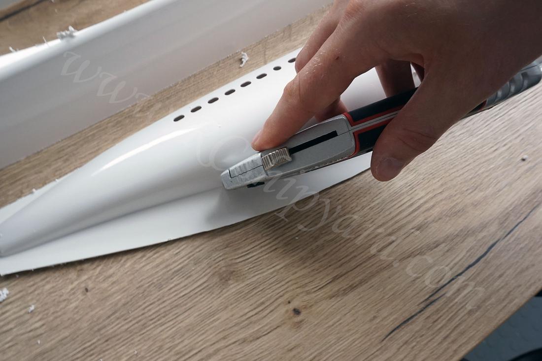
When the groove is finally visible it becomes very easy to simply break out the remaining extensive material. Of course these steps have to be repeated for each of the hull halfs.
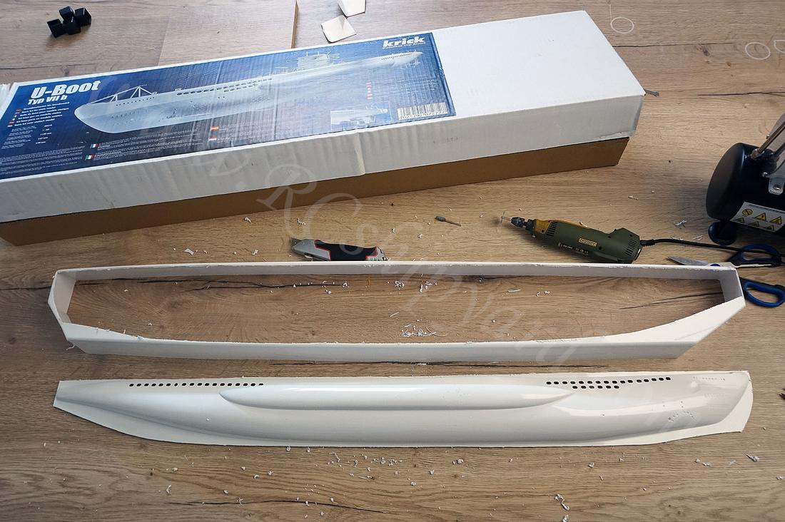
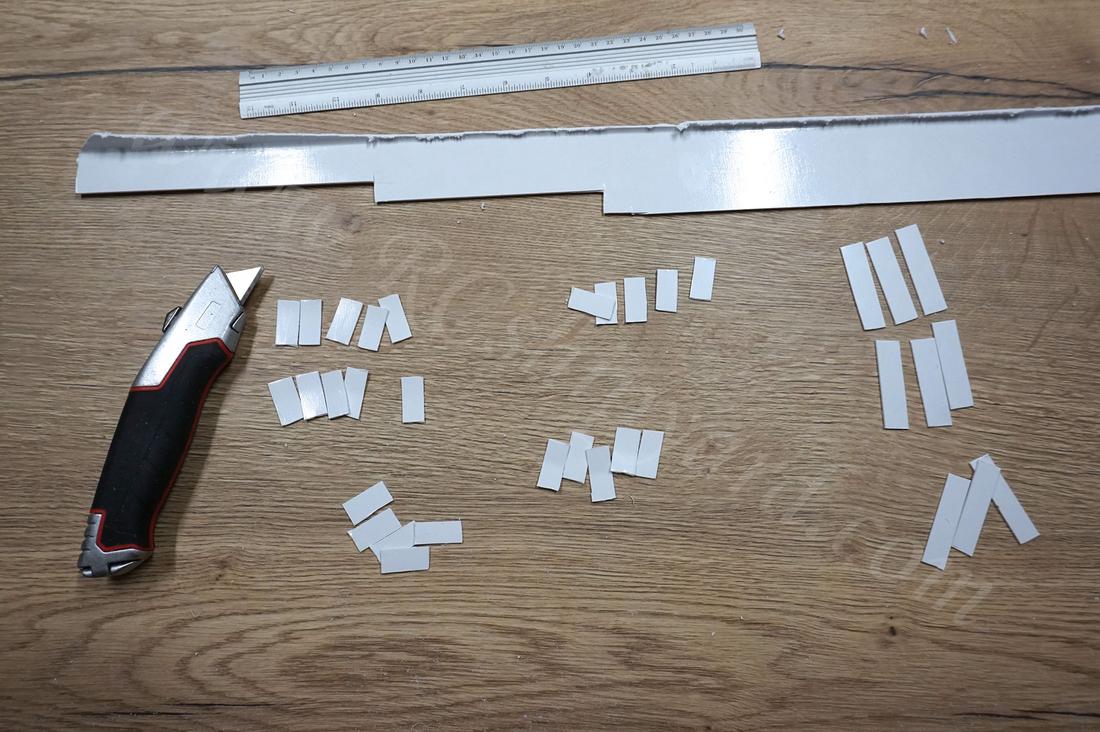
The leftovers from the hull are still quite important so I’m not throwing them away. They’re required to cut out strips of ABS out of them. They’ll be used to glue the two hull halfs together.
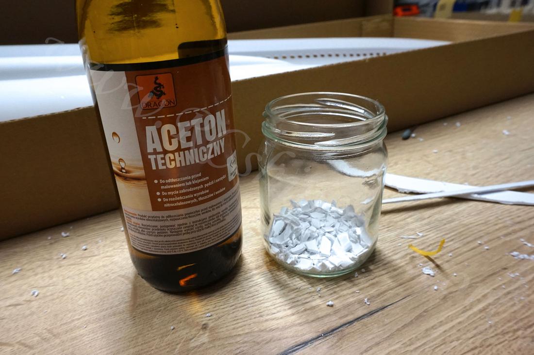
ABS can be picky when it comes to adhesives. Of course epoxy and CA glue work fairly good, but what works best is melted ABS. You simply have to throw small pieces of leftover ABS into a jar and pour it over with acetone (close the jar). The amount of acetone poured will affect the consistency of the “glue”. I like mine fairly sticky, so I don’t add acetone to much. Acetone is a moderate health risk so don’t breath it.
When the glue was ready (about 12 hours later). I’ve used it to glue in a row of cut out earlier ABS strips into each of the hull halfs.
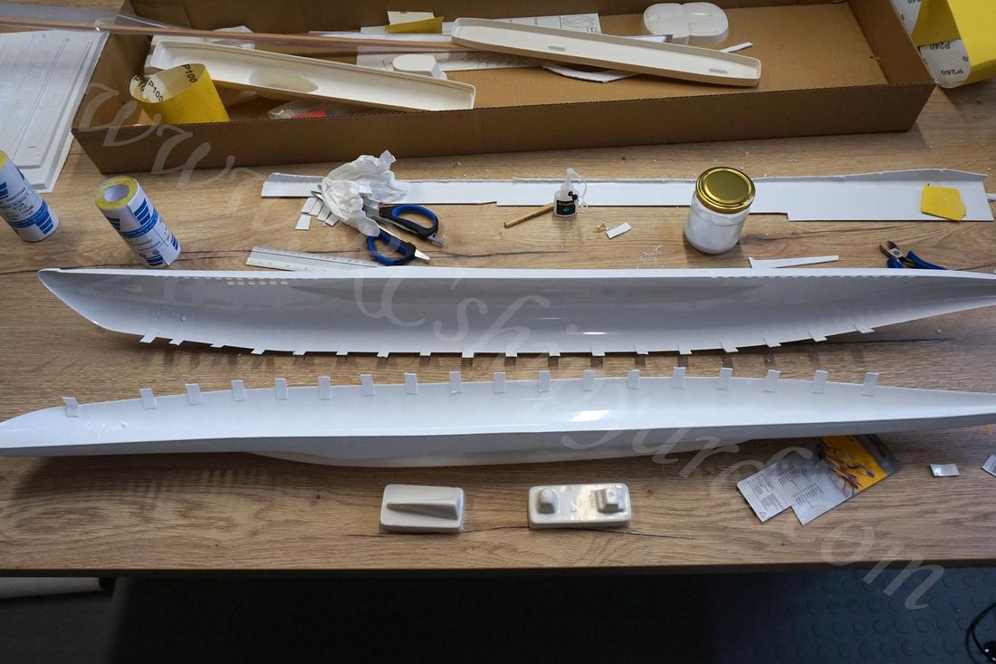
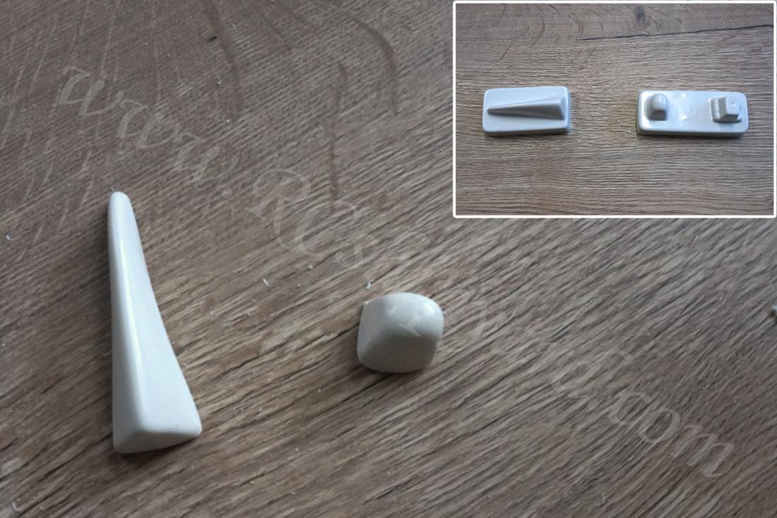
In the KIT there are two weird looking elements which I used to call “noses” cause of their funny shapes. It’s worth to remember that they have to be glued into the ends of the hull. The smaller one goes to the stern and the bigger one goes to the bow.
At this time is also worth to assemble the keel, as it will be the spine of this boat and it really has to be straight and tough! Of course the first task is to cut it out from the additional material:
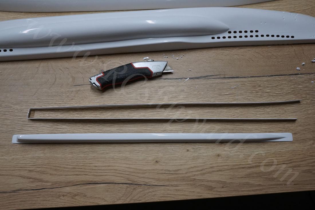
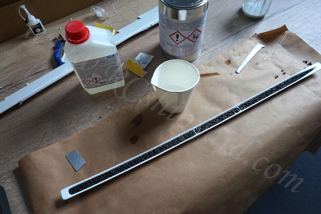
Then it’s time to fill it with lead ballast in a shape of little balls. Sadly, Krick doesn’t supply any ballast. I do have quite a stash of that, but still in my opinion it should be supplied with the KIT. To fix the balls in place I’ve used epoxy (also not supplied). The funny thing is that it’s impossible to fill up that shape with the amount of lead balls which the manual states. It’s simply two small!
Lastly it was time to cut some support elements for the removable middle deck section:
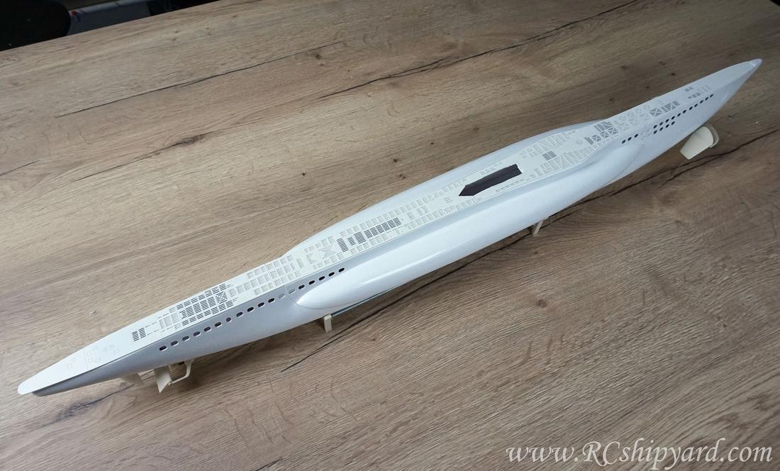
Of course to fix in place the elements from the above photo I had glue together the two hull pieces and then cut the deck opening first. Gluing the two large hull parts is very easy when you have the strips of ABS in place as they inter lock with themself, but cutting out the opening in the deck required more patience than earlier ABS “breaking off technique” as the knife path is rather difficult cause of the hulls shape with occasional sports with no knife support.
Little clamps help greatly at various states of this build.
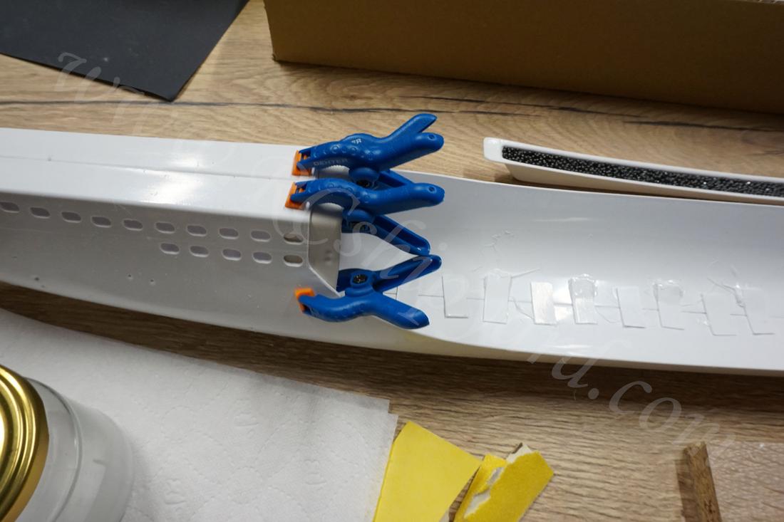
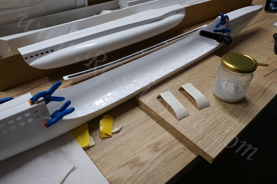
With the two hulls glued together it was time to fill the outer gaps around the hull – bow, around the keel and at the stern of the boat, I wanted to make this rock solid so I used quite a lot of my ABS glue with intention of sanding it down flat later.
Bow:
Keel, here I have used lots of ABS glue. This thing is the spine of the boat and has to be solid as a rock!
And finally the bow. I was very happy as I was able to this extremely straight without any warping.
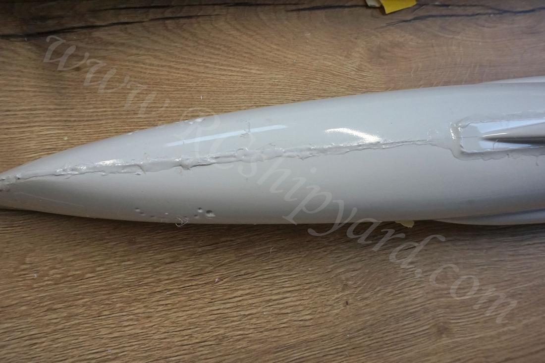
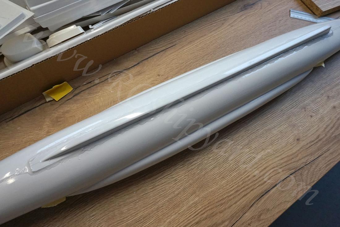
When the ABS glue was finally cured it was time for sanding away the excessive amount of it. I must say it was a rather long and boring process, but it ends with great satisfaction. Bow is smooth like porcelain.
But something unexpected happened around the keel. No ideas why, but there are lots of bubbles in melted ABS. The bond of the keel with hull is solid, but these bubbles wherever they came from will have great impact on sanding time.
For now I have covered the bubbles with Tamiya putty on side, I’ll sand it down latter when it dries and check the result. Not really worrying about it at this moment, as it’s just one of those problems which only require some extra time to deal with.
Still I’m happy with the result of stern, as it requires only some finer sand paper and will be finished. I had to put quite a lot of ABS there as my hull parts were not the same length. One of them was shorter quite a few millimetres than the other.
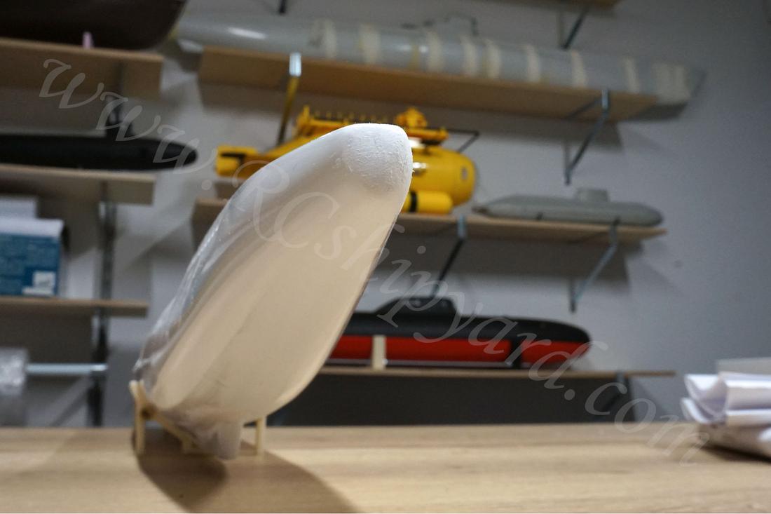
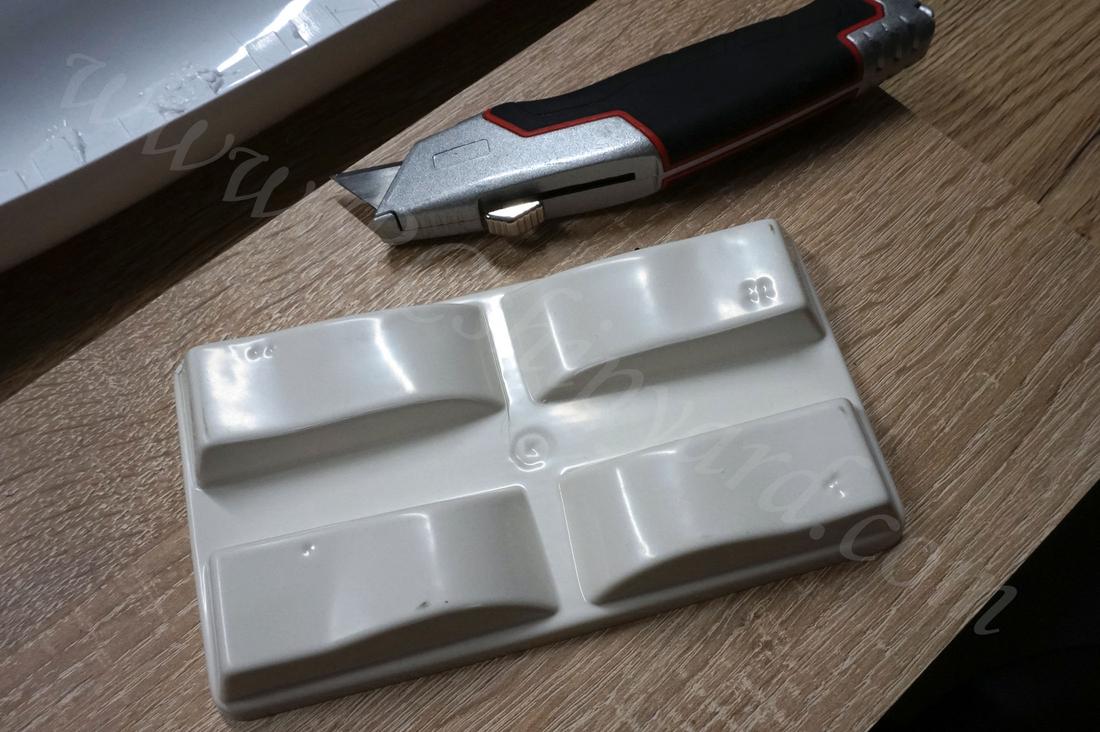
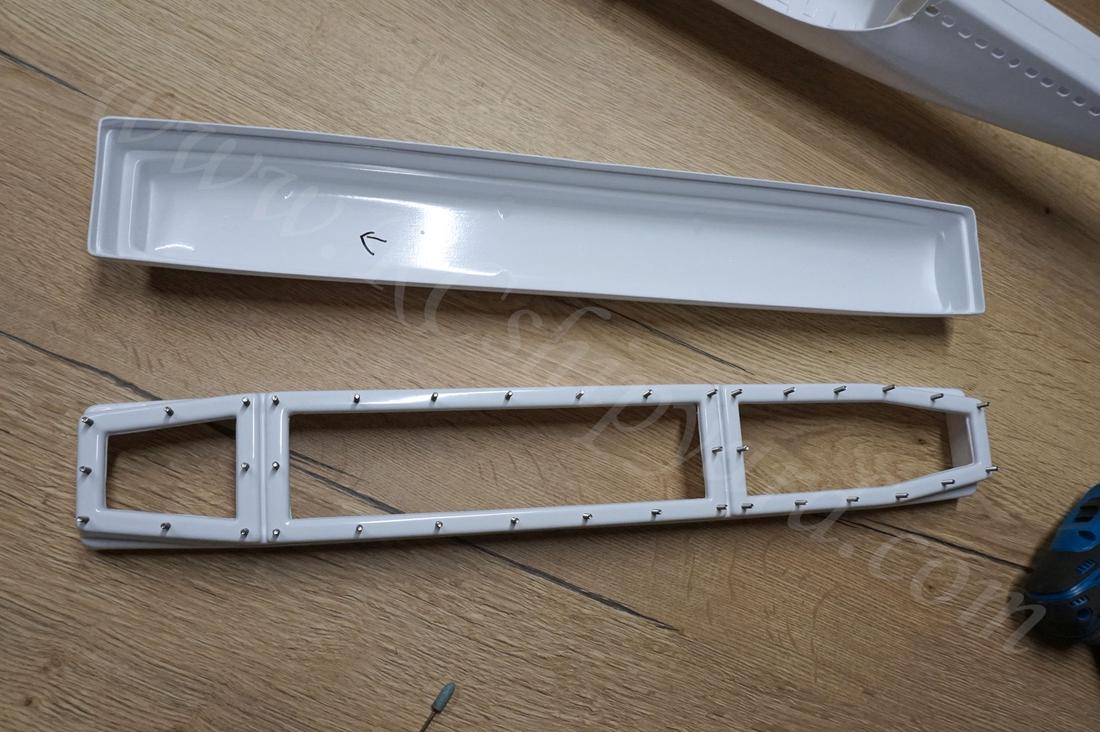
3. Water Tight Container (WTC) – assembly part 1:
The WTC of the Kricks VIIB is also made out of ABS and it’s in shape of a box. The extra material had to be cut out to allow a fit of the upper part with the lower one. I honestly had no clue which is the correct cutting line, the manual is so unclear about that. I decided to cut of less just in case.
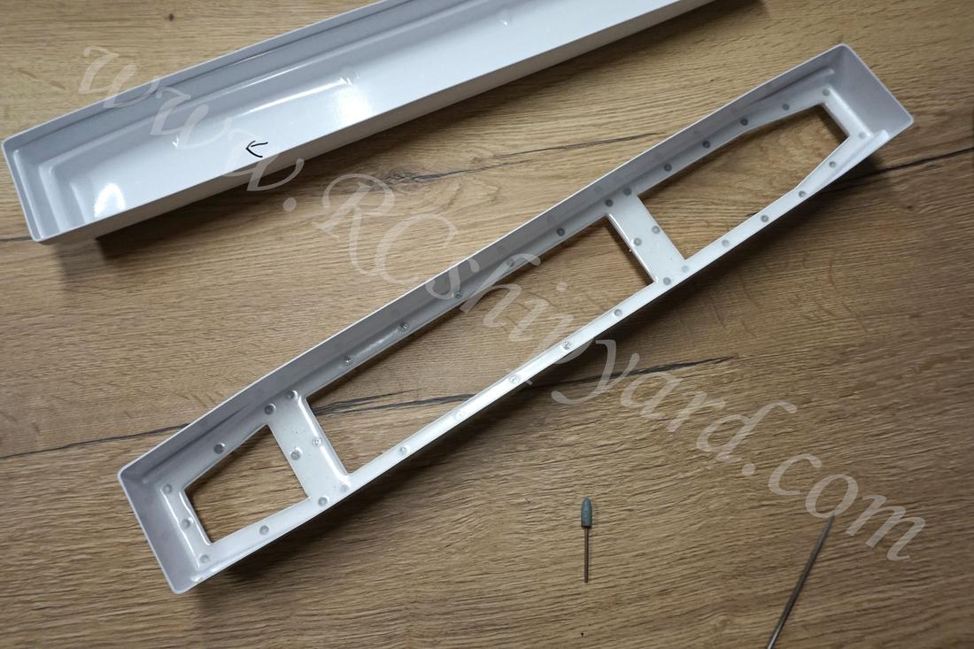
*Edit from “future me”: Yup I have cut less than I should. Read this chapter carefully to avoid my mistakes because of the vague manual. More info further in the building log.
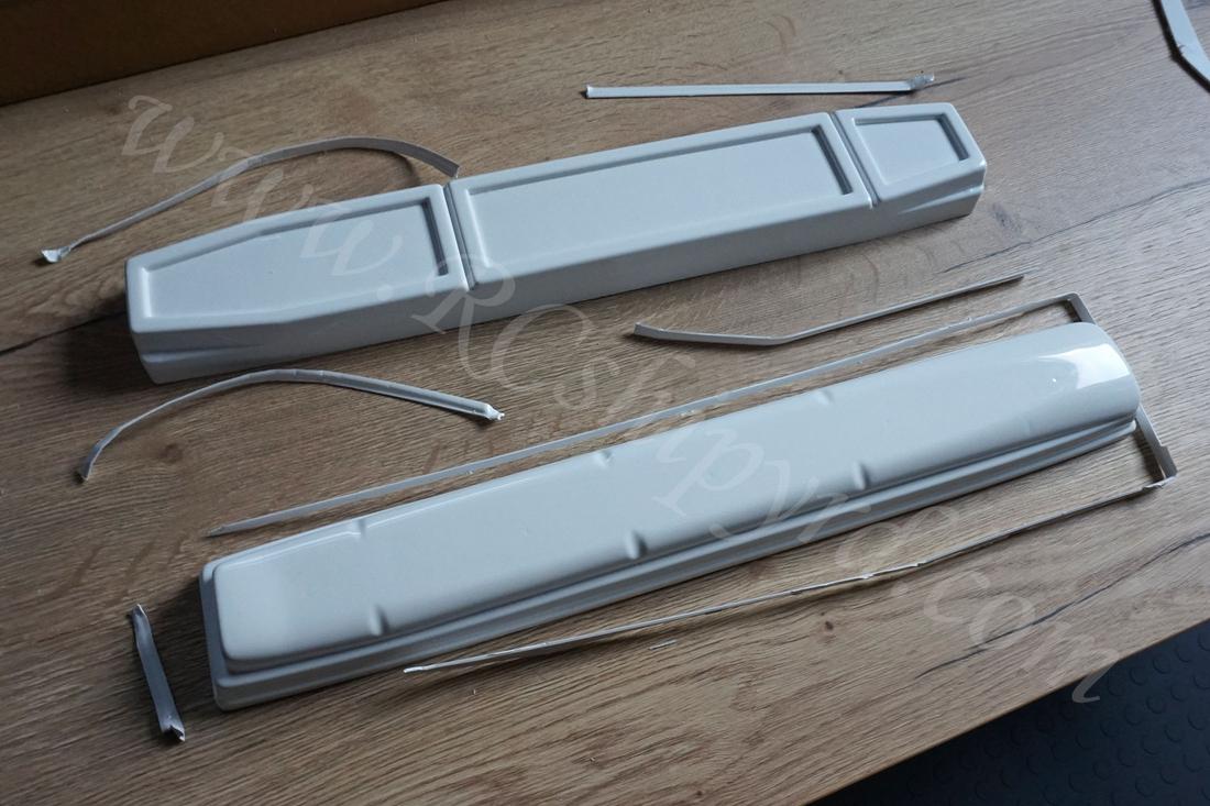
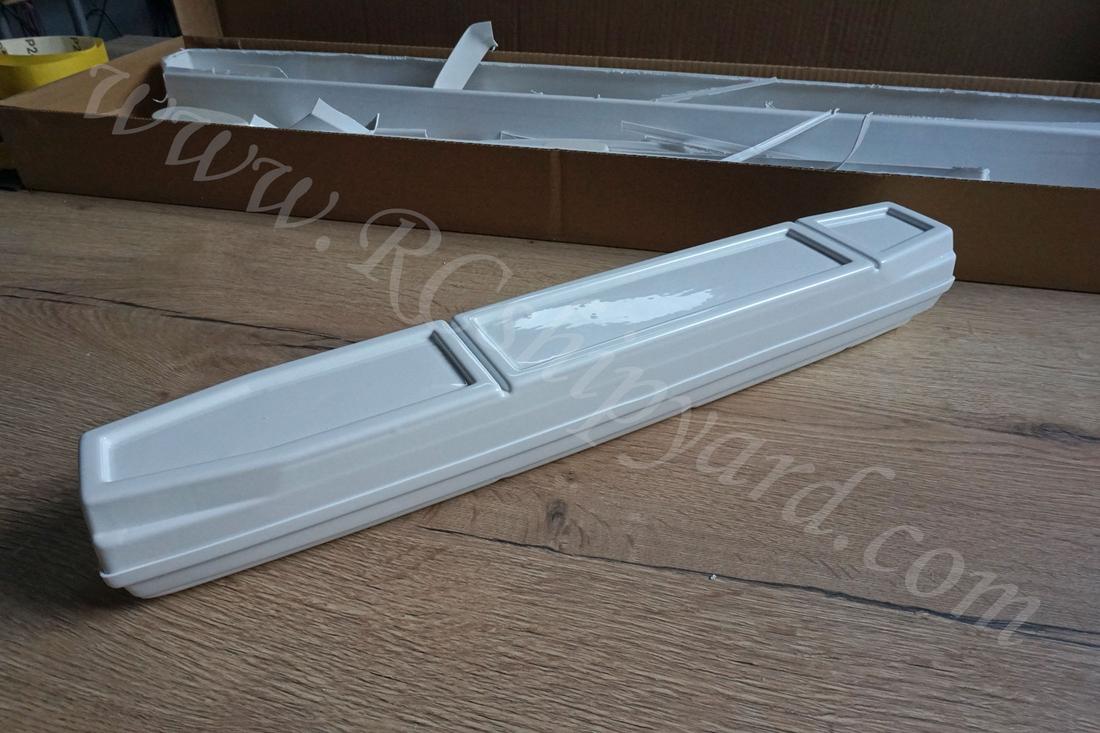
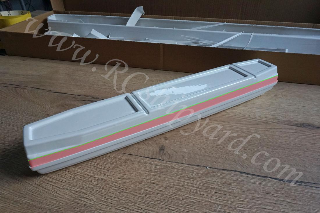
So at this point it looks like it fits perfectly, but as I’ll later learn this thing is still to high to fit the hull and in current shape it will not allow to close the upper deck.
On this photo I have marked my mistakes. If you have the KIT, you already should know that the dry section is constructed in such a way that the upper part partially slides into the lower one. The problem is how much it should go into the lower section because of the unclear manual. With the red colour I have marked the ABS material which should not be visible – that means it should be partially removed and the rest slid into the lower section. When you do this the green line should be aligned with the upper edge of the lower section.
I was unlucky enough to get the Acrylic windows without the holes drilled in them. As I have been informed by other model makers, most KITs come with the acrylic windows already with the holes in them. Oh well, not a big problem as I’ll be able to make the drilling pattern from the neoprene gaskets.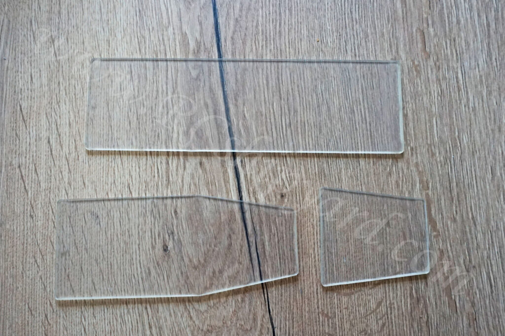
And that’s how it looks with all the holes already made. It’s worth to mention, that I’ve used the acrylic glass windows as patterns for drilling the top part of the ABS made WTC.
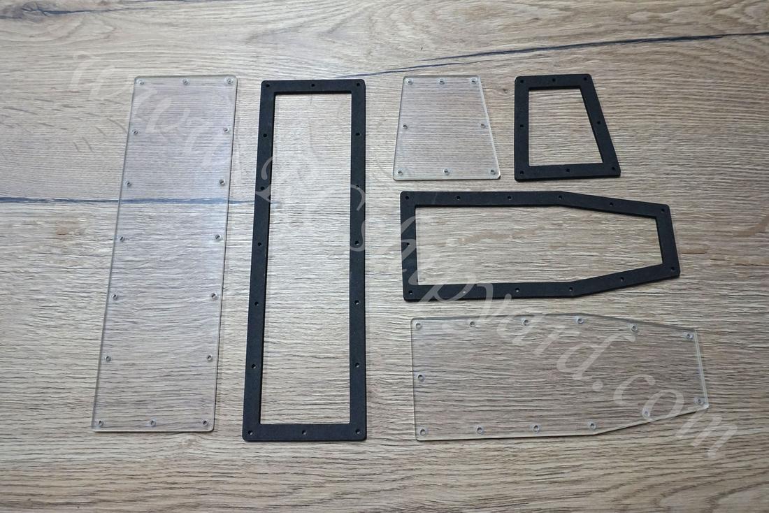
The window slots in the top part of the WTC have been cut out. I have also drilled and inserted the screws which will keep the windows watertight.
The manual says that I should glue in the supplied wooden bars, but I decided upon a different approach. I placed pieces of fibre glass mat and some fibreglass rods in the groove. Then I poured epoxy into the groove to about 80% of the grooves height. Drilled the damn thing together with the acrylic windows – all taped together. Then if poured the epoxy to the remaining 20% to make the screws and their threads watertight. That’s the Engels way dealing with that, worked for me in their boats, so should work now too.
I have glued the two pieces together using epoxy instead of my ABS glue in case I’ll have to split the two parts again because of the unclear line of cut in the manual. That was a very good idea as…
…as in the end I had to reopen the dry section and glue it together again. It was a tough job, but doable. Very, Very poor manual and someone at Krick should lose his job for accepting such vague descriptions:
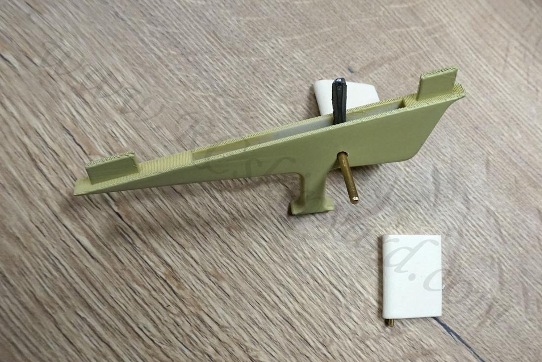
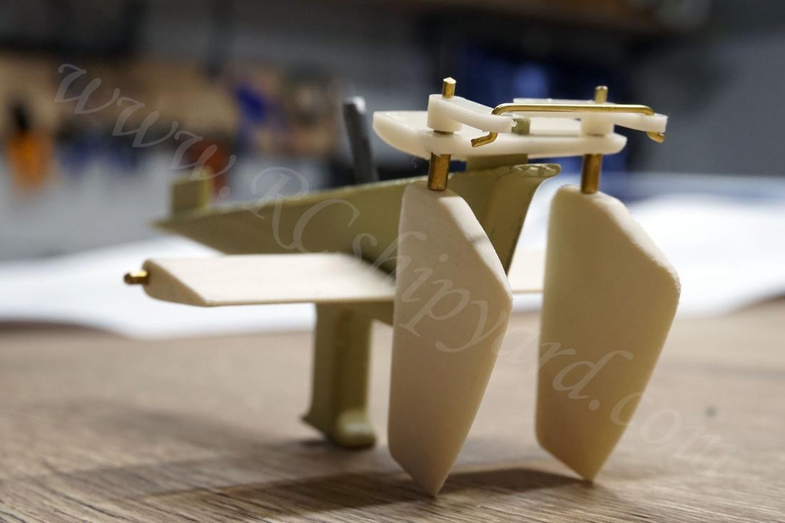
4. Rudders and stern dive planes – part 1.
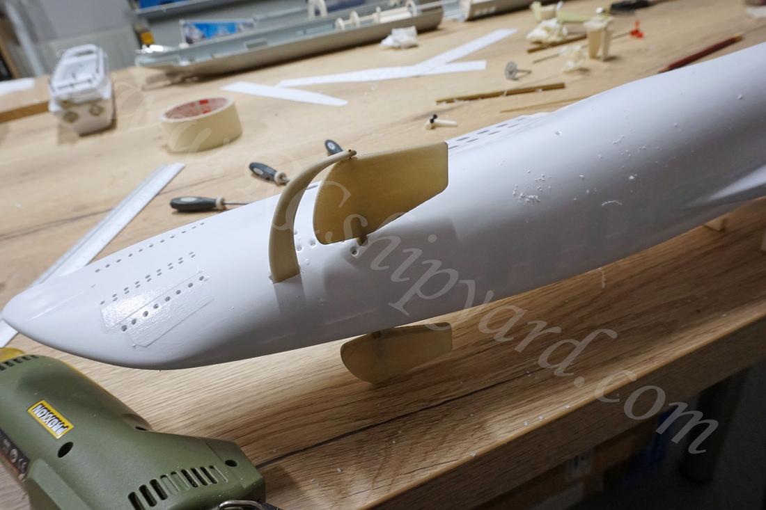
While going further into the build I was absolutely shocked that Krick designed this model with the non operational stern dive planes – both fixed permanently in horizontal position. I fully understand the idea of the “classic type” model ship kits in which you have to shape everything from pieces of pre cut ABS or polystyrene, but in this case it’s to much of a simplification. The green numbers 1 and 2 mark the elements which Krick proposes as dive planes. No way I’m going to leave it like that! Time to CAD something!
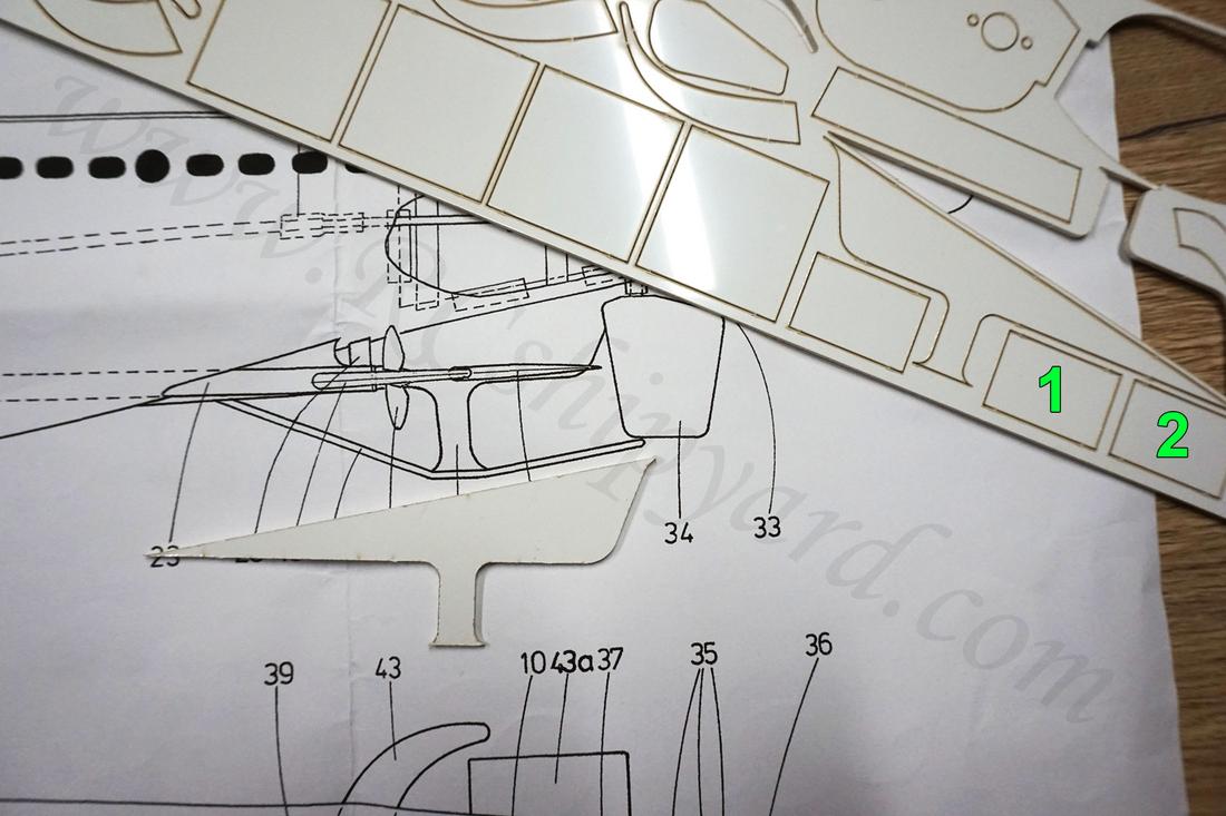
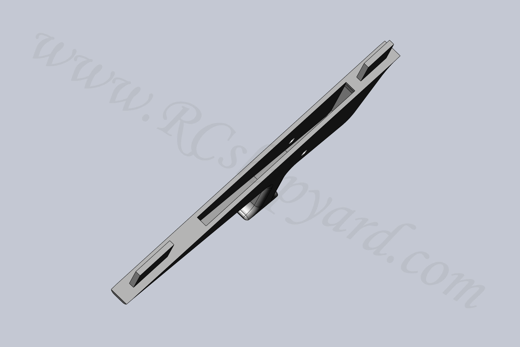
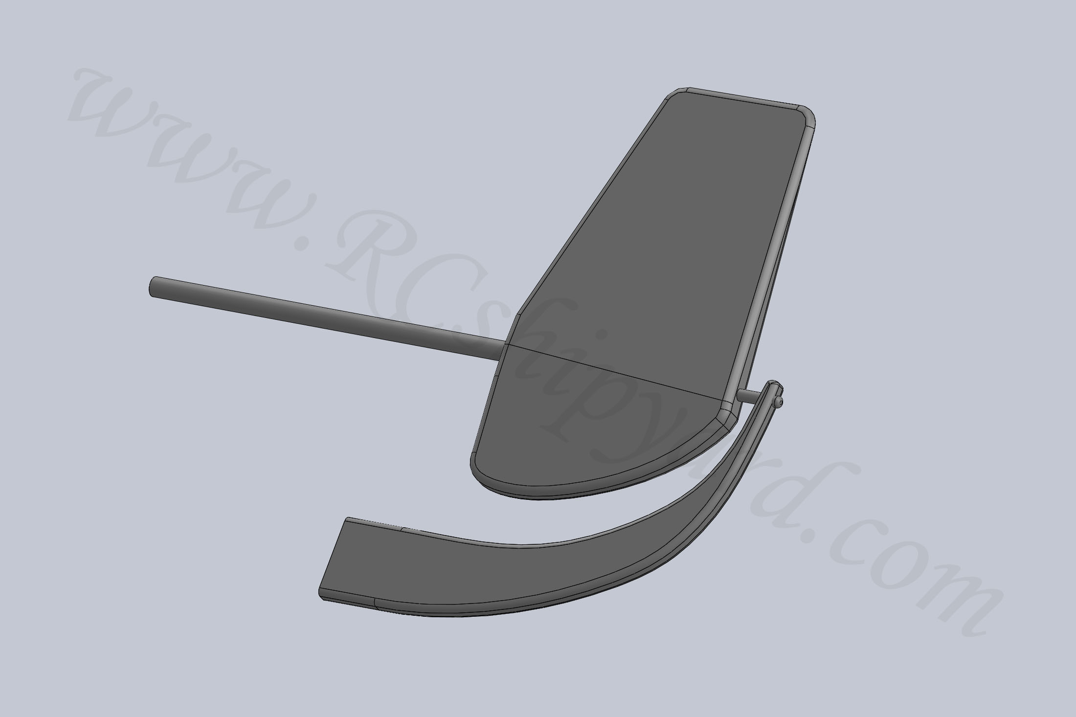
The idea was to design a new element with a slot for the dive planes pushrod lever hidden inside. On the bottom of the element there’s a hole for the M2 screw for future additions, as type VII boats had a quite complicated dual rudder system with lots of additional elements around them.

The slot is 3mm wide, which perfectly enough for a lever. The whole part is 7mm thick. Of course I had to design the stern dive planes too. They’re slightly larger as I’m a fan of some extra manoeuvrability.
After the design process it was time to print it. I use FDM printers, which are more prior to slicer software errors – especially with angled surfaces. That’s exactly what happened with the print #1:
Luckily after some fine tuning, I was able to get a nice sharp line:
Then some spray putty, sanding paper and we have a nice smooth surface and a well conserved part. The dive planes are much easier to sand down, so they don’t require the extra work with putty. Just some mechanical sanding. All of these are solid parts, but to print solid parts you have to take this into account already while designing a part, not simply setting an infill in the slicer.
The STL files for this part can be downloaded HERE
Of course I was still missing the dual rudder system. Again the design comes first:
The STL files for this part can be downloaded HERE
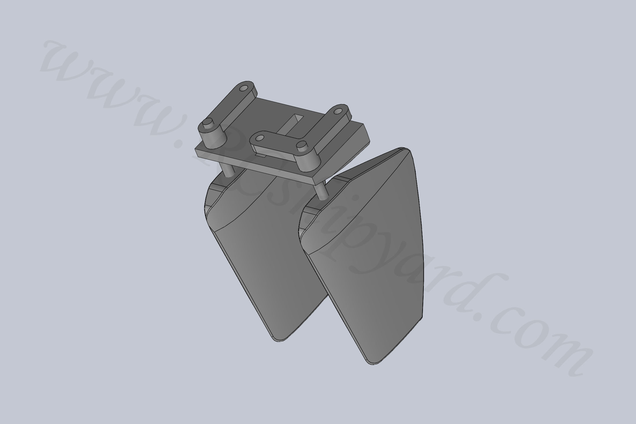
Then a quick 3d print, smoothing and the initial assembly without any glue yet:
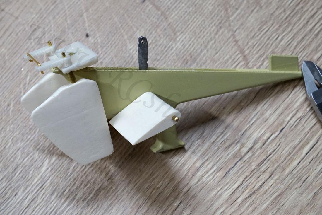
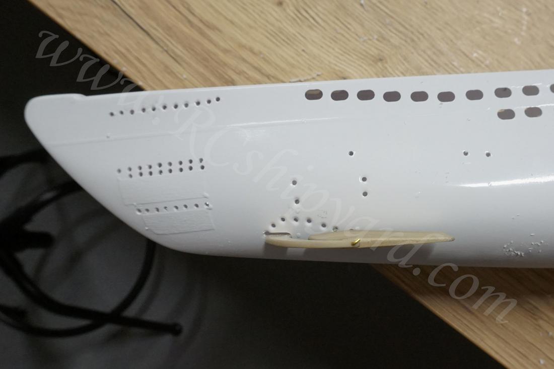
5. Bow dive planes
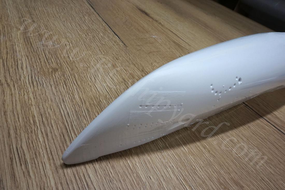
With the bow planes it’s a similar situation as with the stern planes – the ones provided by the manufacturer are simply to primitive for me, so I had to make myself a new set. A quick design:
And the final part ready for assembly, this time I used a rotary tumbler to smooth the parts out. The only disadvantage of that is that the parts have to be cleaned quite thorough after the process. The planes are slightly larger then they should be, as I want some decent manoeuvrability, which type VII models usually lack.
The STL files for the bow dive planes mechanism can downloaded HERE
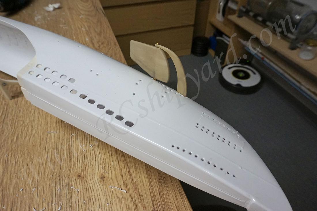
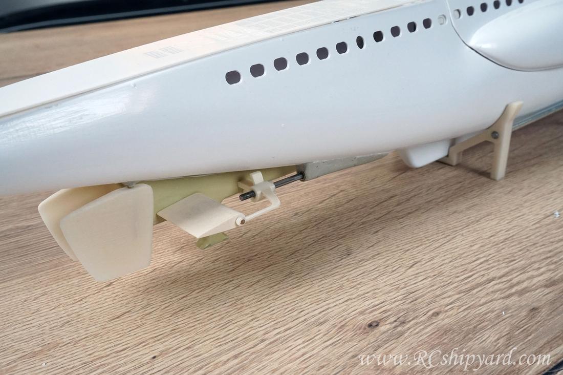
Fixing the bow dive planes with the hull:
Getting ready to mount the bow planes, double checking the alignment etc.
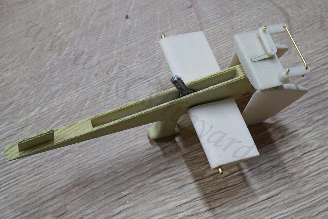
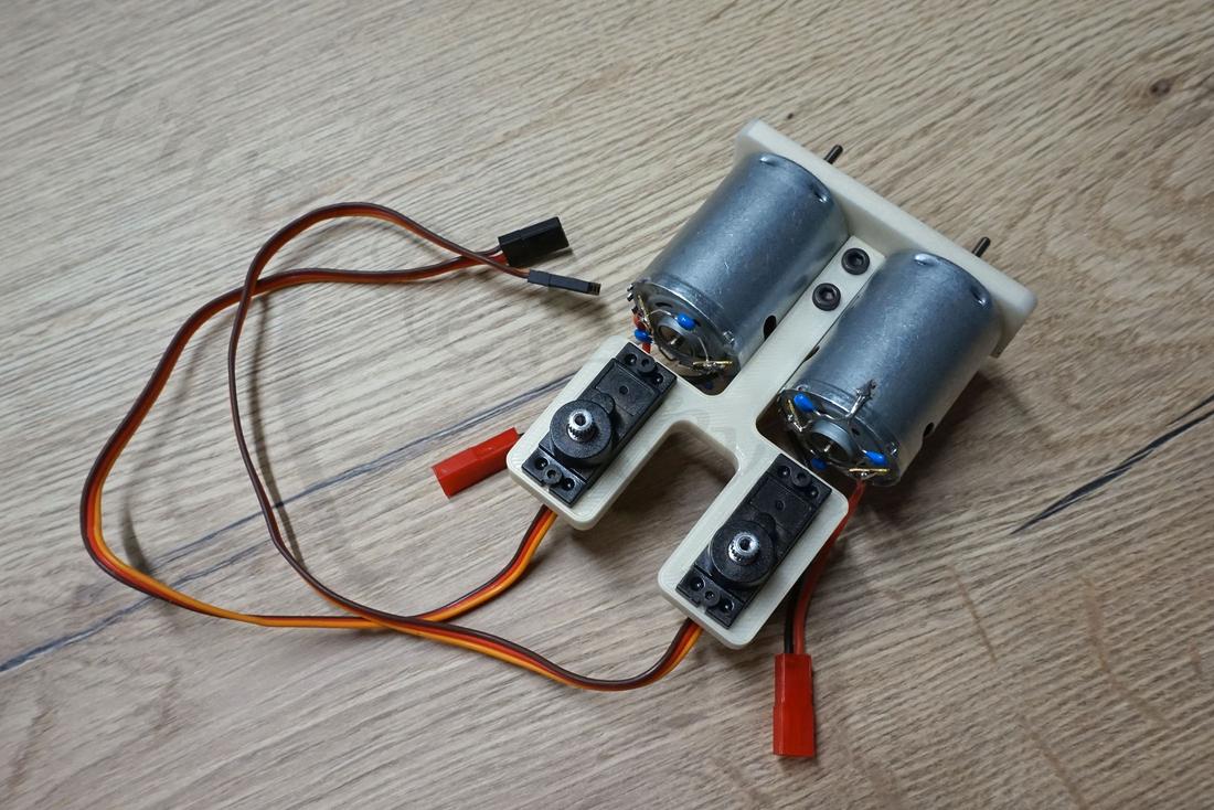
6. The motor block.
Krick’s idea is to use two motors with a direct drive. That seems alright, as I was never happy with gearboxes splitting the power from one motor into two separate shafts. The mounting plate for the motors is pretty alright too, but I made myself a new – thicker one:
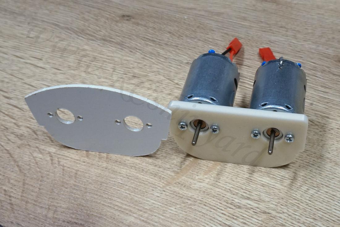
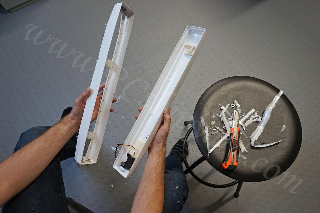
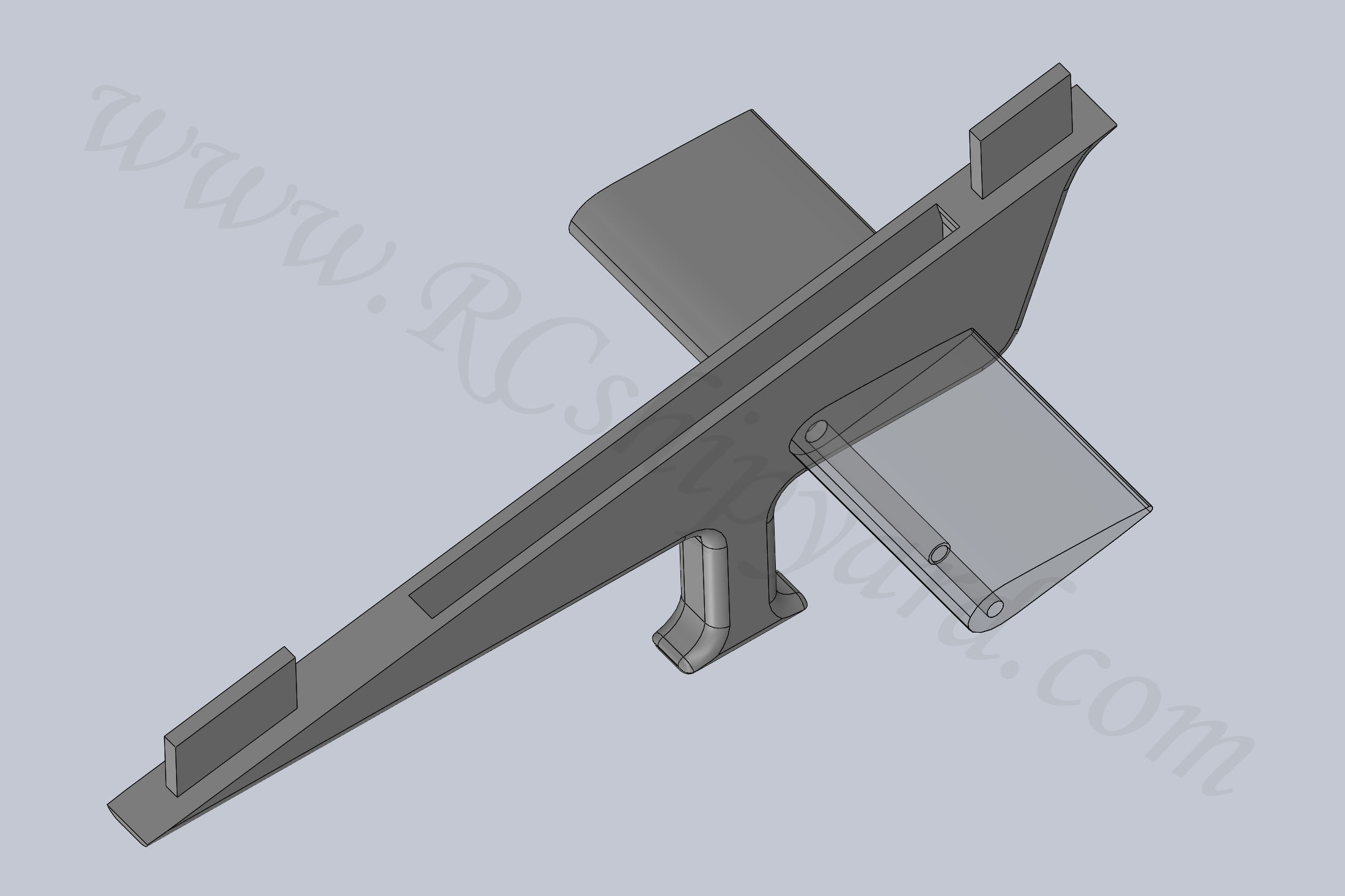
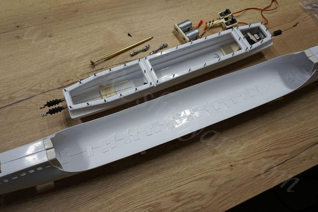
The new motor plate from above would work alright, but at some point I had a much better idea… I wanted a better flexibility – in case something breaks. Now, when using the original motor block (or mine thicker one), after gluing in the motor board into the WTC (as the manual says) I would end up with a very limited access to screws holding the motors in place. It would be very difficult to replace the motors in case they break. I wanted to be able to remove the whole motor block from the top, plus some mounting slots for the stern servos would be nice too. So back to the drawing board:
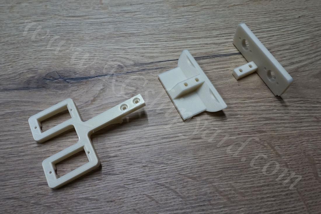
My idea was to make 3 separate parts (left picture), servo block which obviously holds the servos, motor block which will keep the motors in place and the middle part will be the only non removable part glued to the bottom of the WTC. They all combine into one multi purpose block (right picture), which is easy to disassembly and removal from the top by using the Allen key
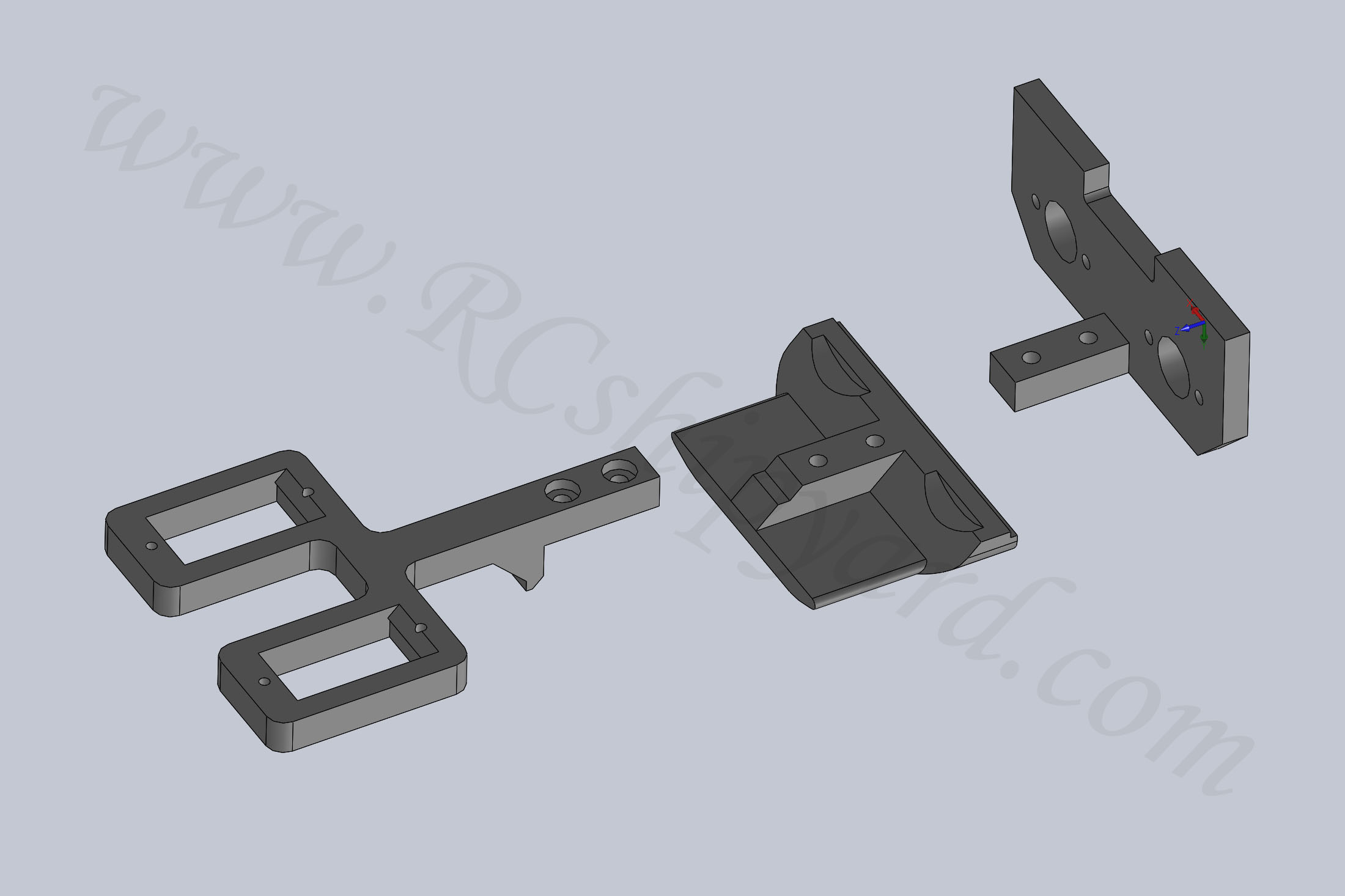
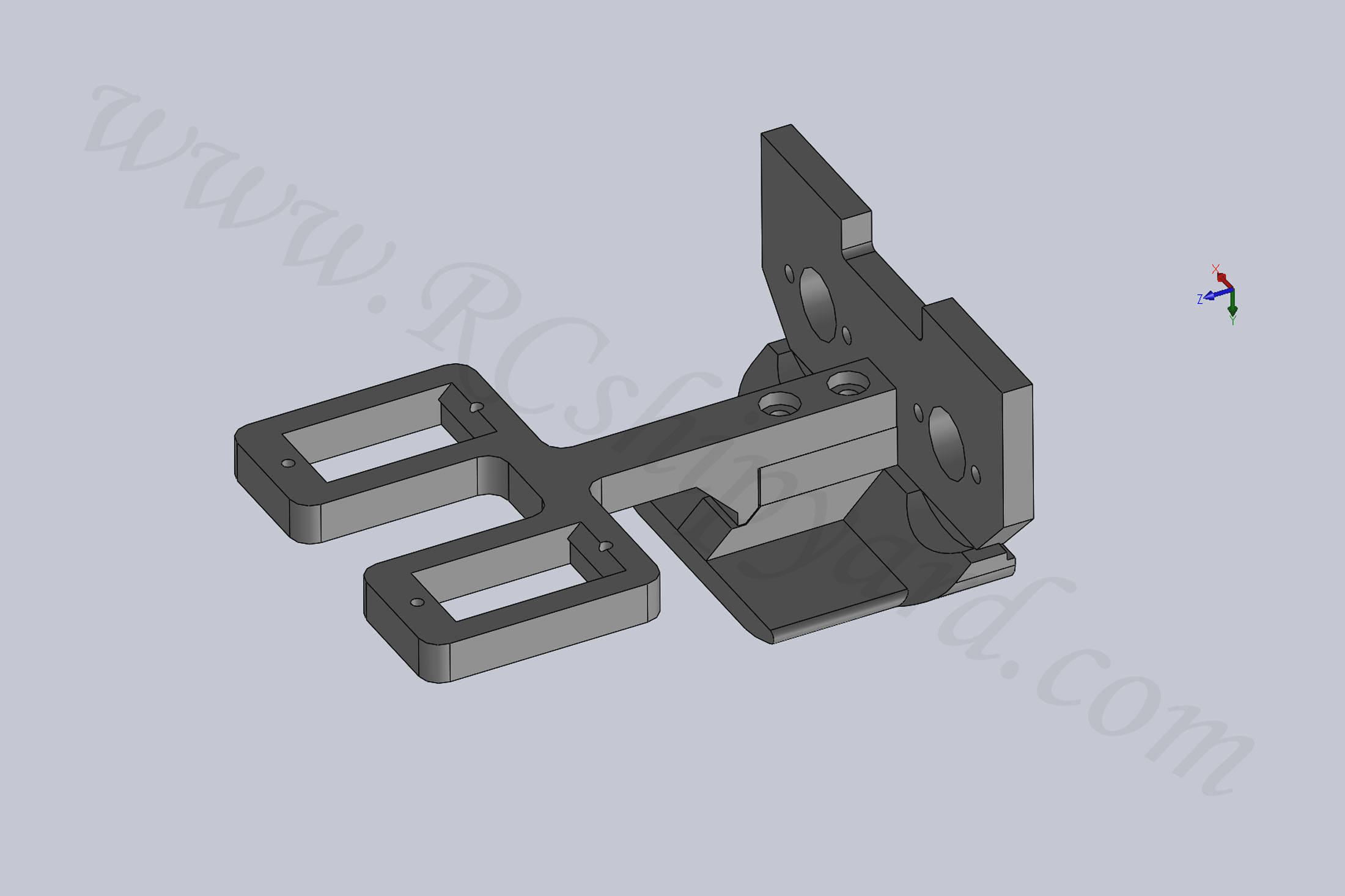
3d Printed elements (left) and fitting in the RC equipment (right) :
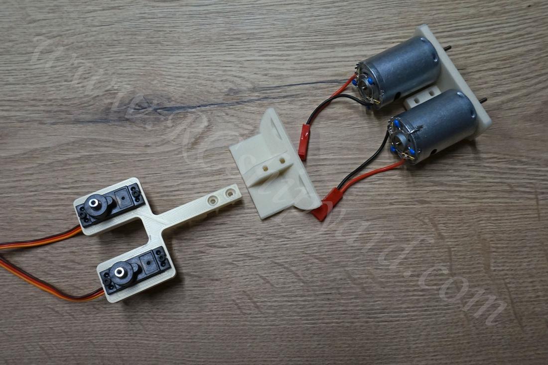
Assembling it all into single block:
The STL files for the motor block can be downloaded from HERE
And of course a trail fit of the motor block in the WTC.
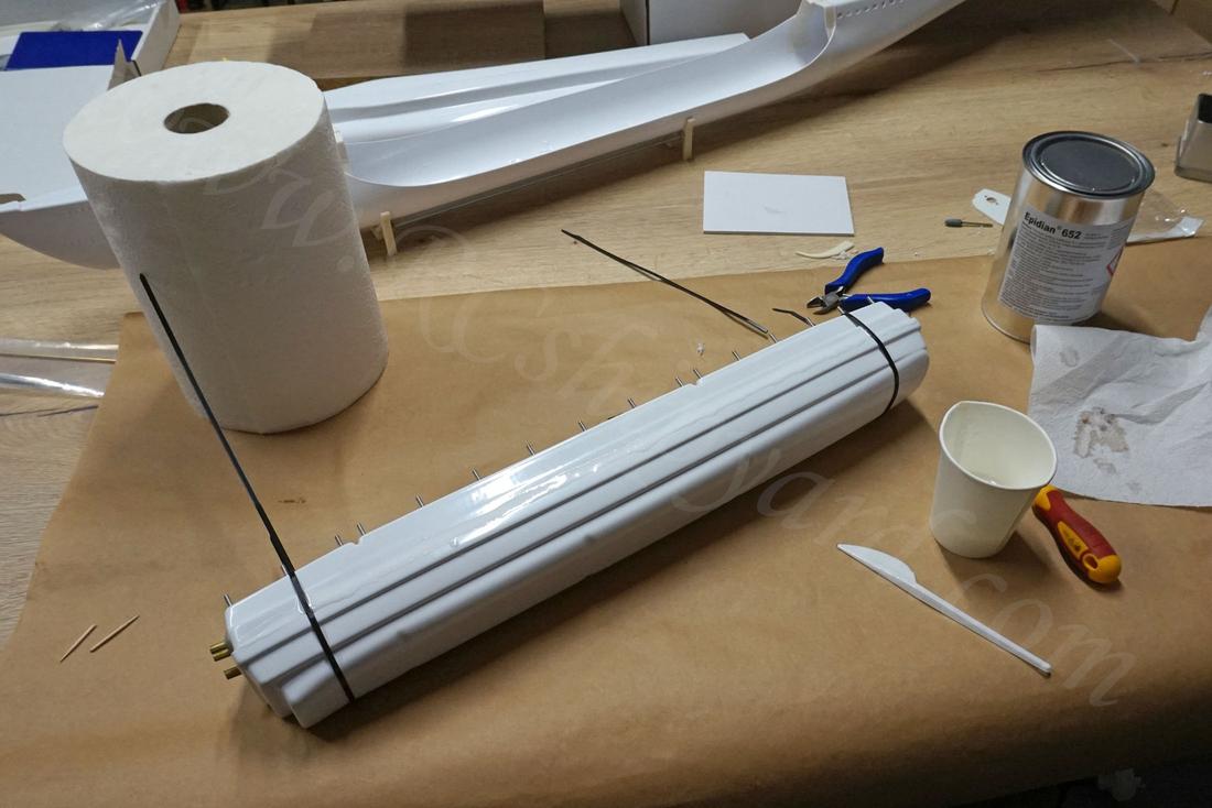
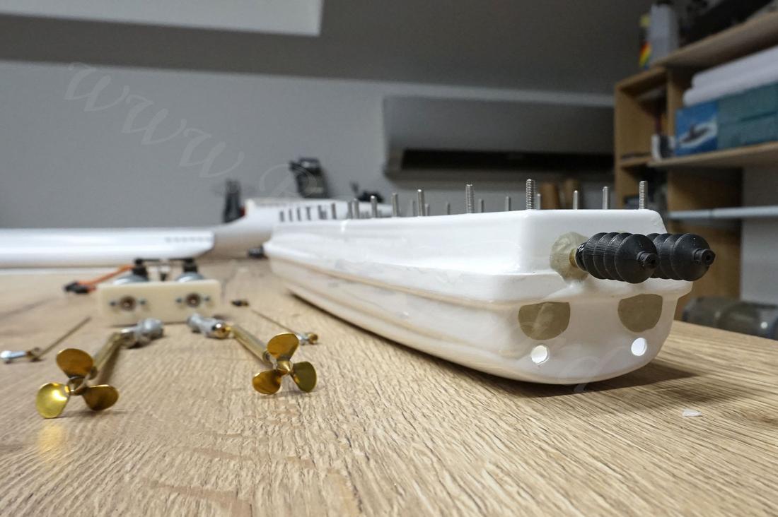
7. WTC assembly – part 1.
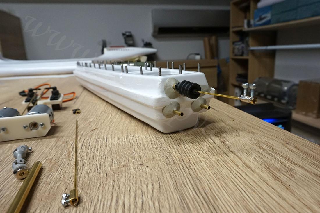
So here I’m trying to arrange everything in my head, also at this point I have ordered and received two new shafts with brass props. Both shafts are 5mm shafts with a 3mm stainless steel rods. The thickness of the brass is 0.8mm. That leaves a gap of a 0.2 on each side. This should be possible to seal with thick grease and an oring at the end only, but in case it would not be enough, I have a plan B prepared.
The photo on the left is quite important for whoever will make this model in the future. Kricks manual is wrong, Kricks plan is even more wrong and misleading. If you want the shafts to be horizontal with the boat don’t follow the manual or the plan. I have followed it at first and had to seal the first pair of shaft holes with epoxy putty. Proper shaft output holes in the WTC need to be placed much lower – like mines on the photo (left).
The bow part of the WTC. At this point I have decided to avoid the manual and not to follow it any more. You can see the pushrod for the bow dive planes and the two brass tubes. One tube is for the snorkel while the other is the water inlet.
My model will have a different ballast system than the Kricks idea. Maybe it’s a similar one, maybe not. I’m not going to look into that crappy manual any more.
One last photo before gluing in the WTC permanently into the hull
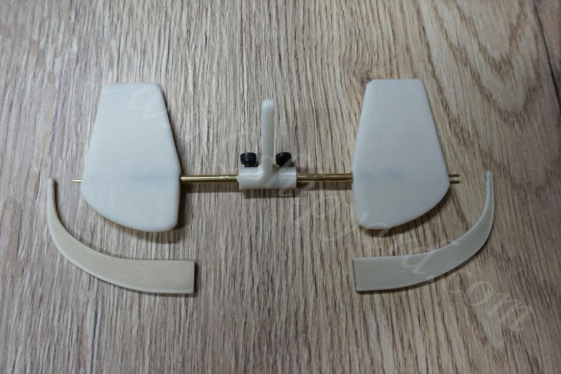
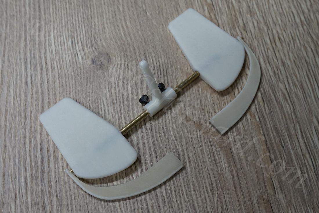
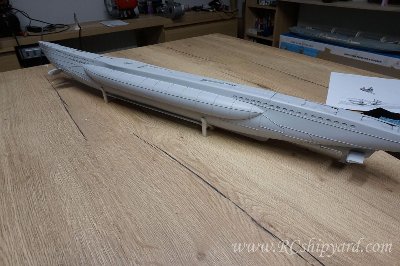
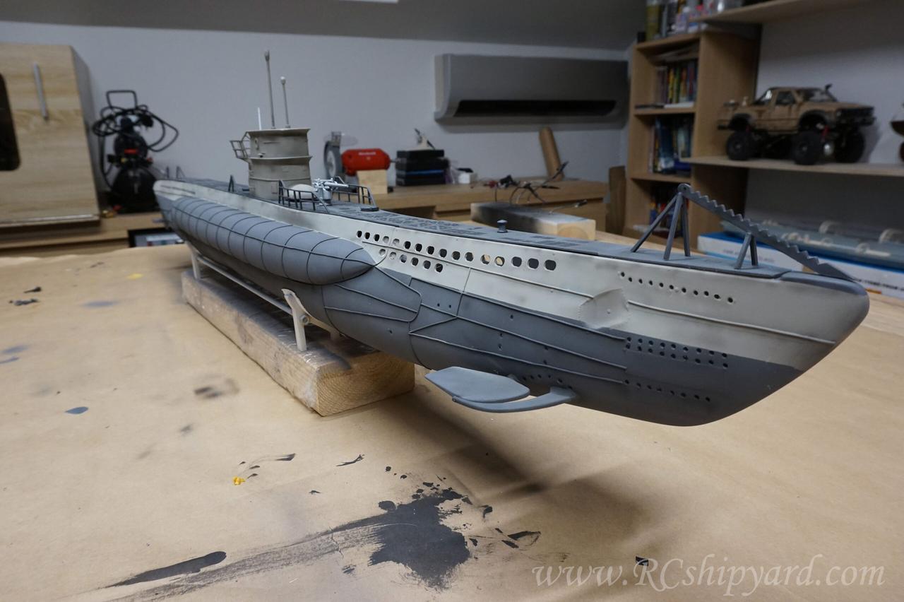
8. Rudders and stern dive planes – part 2.
Even as I’m angry on Krick for delivering such a misleading, crappy manual and unrealistic plans, slowly I’m feeling happy how this thing starts to look. Mostly how well a sanded Tamiya putty matches all the parts together:
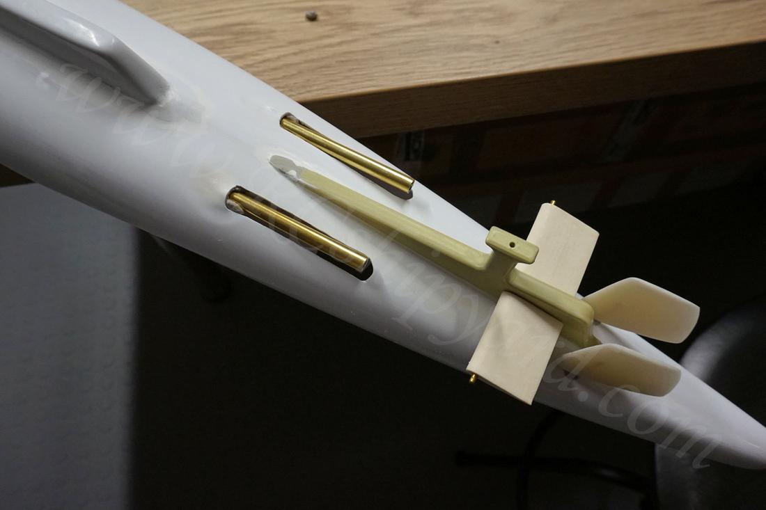
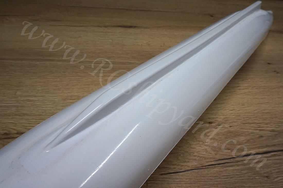
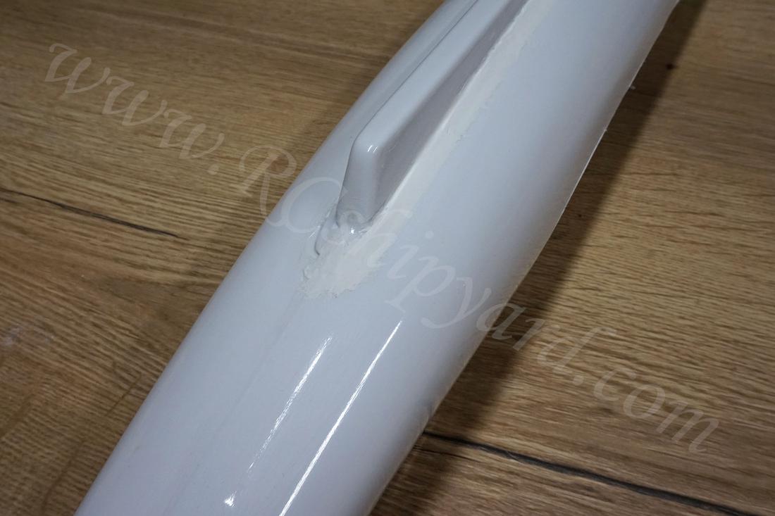
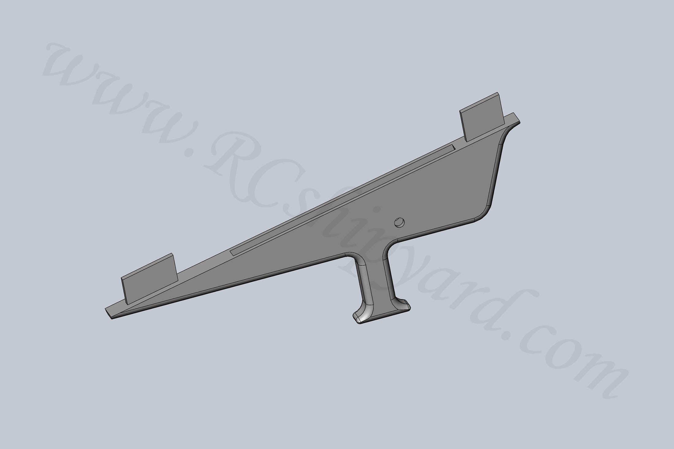
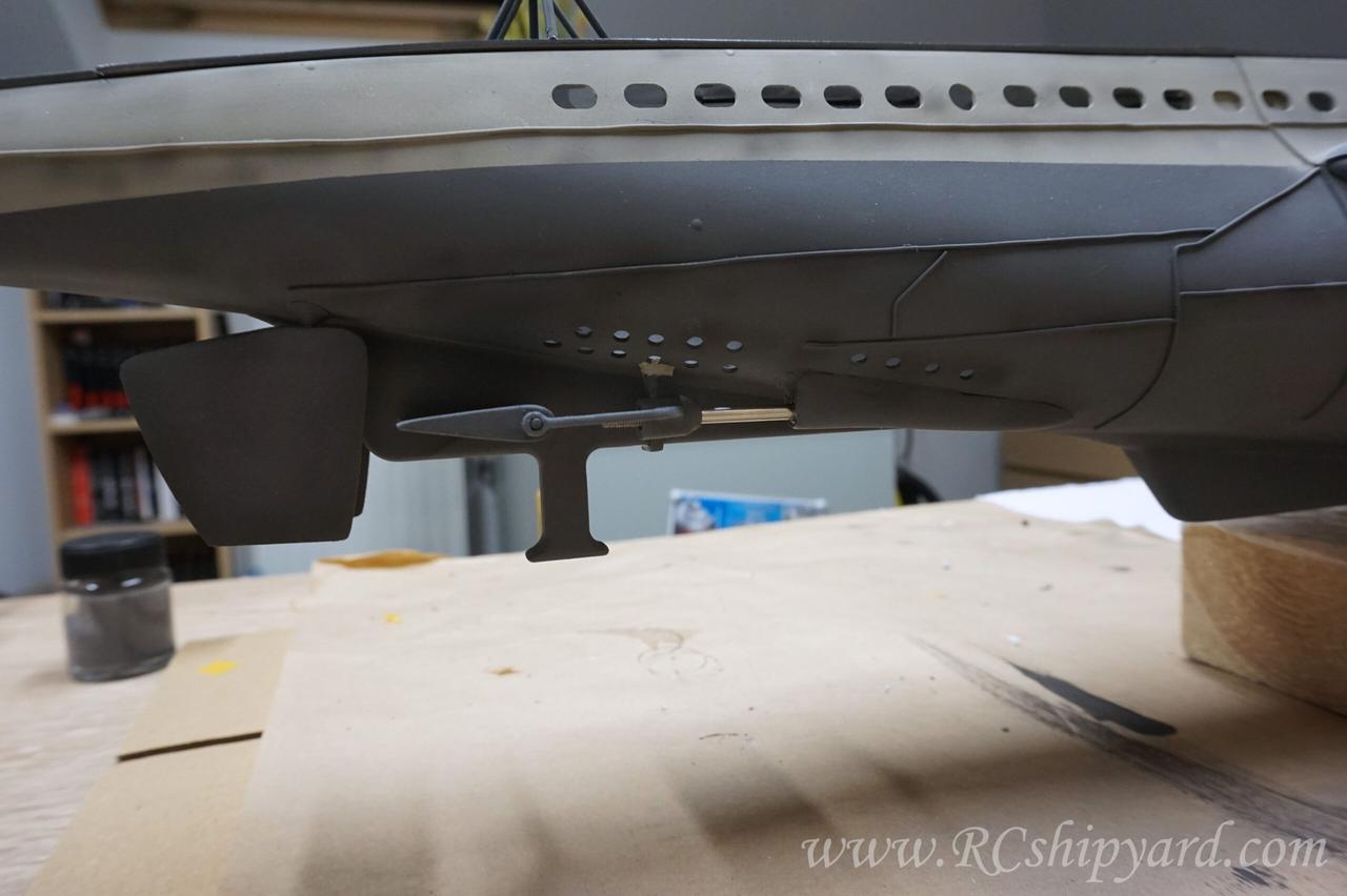
Here you can see the evolution process of designing and printing the shafts/dive planes stabilization element (left to right). It’s impossible to take precise (more than 0.5mm) measurements from the model with such a complicated shape, so hence the trial and error method. Still I was able to achieve it quite fast, 6 prototypes and I was done. The element was hard to design because it has to be collinear with 5 different axis: two shafts, two dive planes rods and the fin in the middle of the stern. The last prototype had a funny bug. It was possible to attach the element to the model but impossible to detach, hence it had to be broken upon removal and redesign for the final time. Maybe I’m wrong but it seems, that Krick didn’t even care to include his own parts for making this element… Quite sad, I would expect more with all that “German quality” myth.
The shape of the stern is totally not realistic and had to be altered. The most important modification was to keep the shafts vertical and cause of that I wasn’t able to fix all the simplifications forced by Krick – the place where the shafts leave the hull has a different size and shape than the original vessel. Still, I did my best and the priority was a proper operation of the boat. I guess I’ll just smoothen the connections/transitions with some Tamiya putty and that’s the best what I could do.
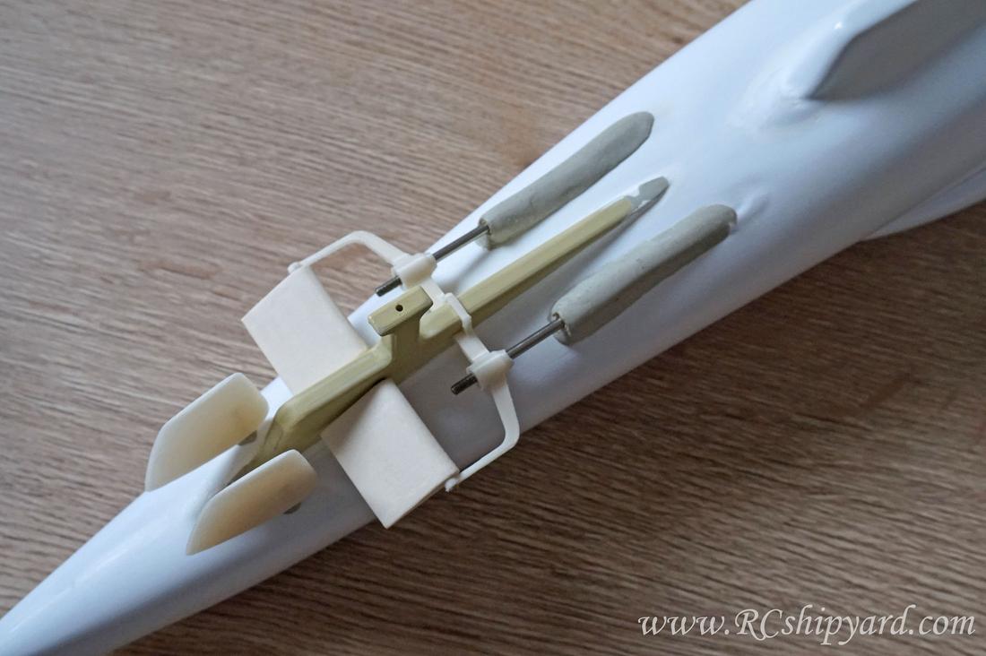
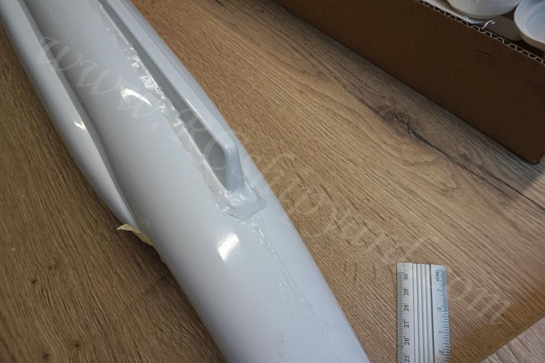
Further works on the stern, the slots in the hull for the twin shafts have been filled with a two part epoxy putty and sanded down. Quite long, but a rather pleasant work. On the photo you can also see already attached the final stage of the stabilization element which evolution has been presented above. It’s function is purely decorative as no real forces will work upon it, but still important as it’s a very distinctive part of German IIWW boats. Still a little gap between that part and the hull, but I’ll fill it with epoxy putty on a later stage.
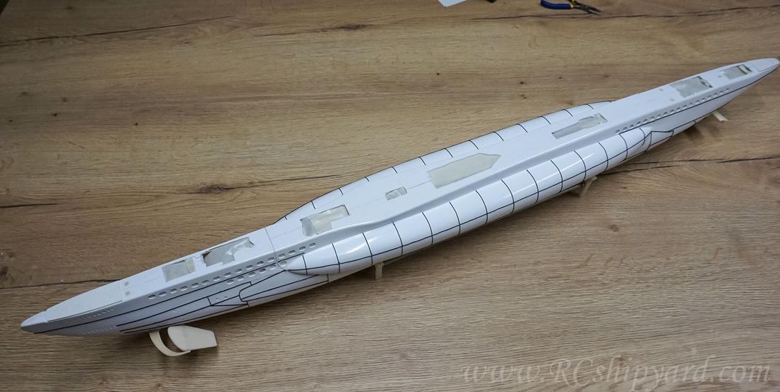
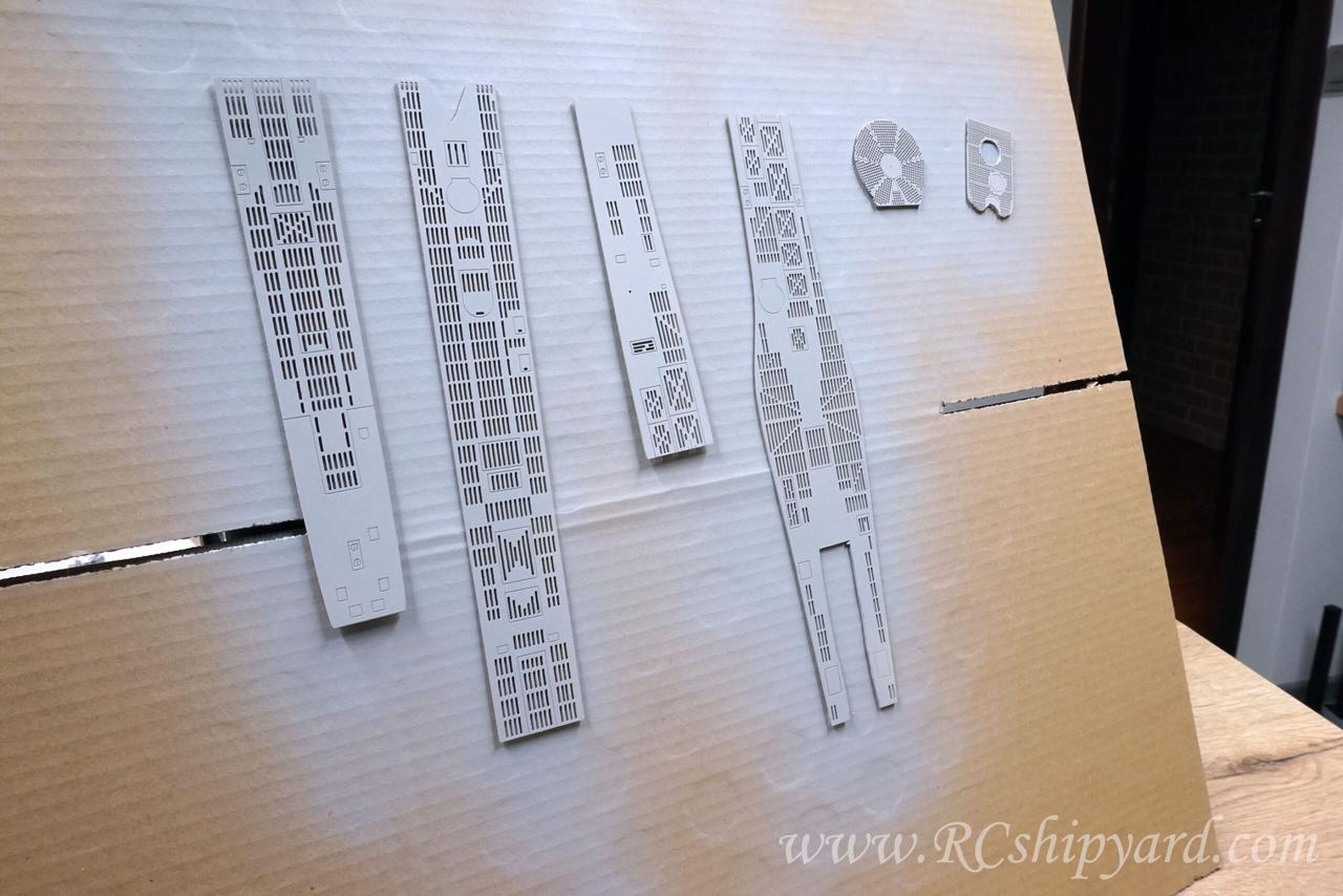
9. Decks
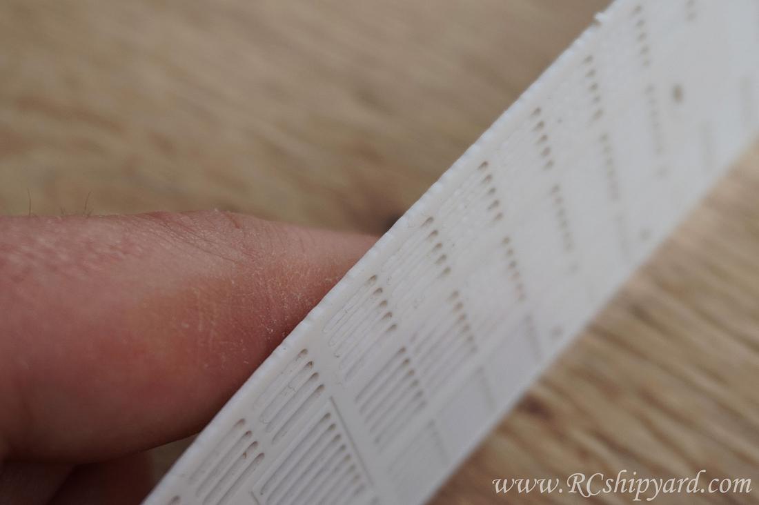
I did cut out the thermoformed decks included with the kit. They feel soft, but they’re at decent quality.
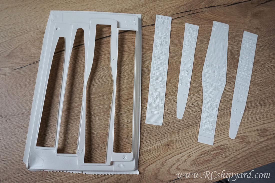
However at some point while browsing the web for information about other building logs of the Kricks VIIB I found milled ones dedicated for this model. So I ordered them. Quality comparison of both decks says it all.
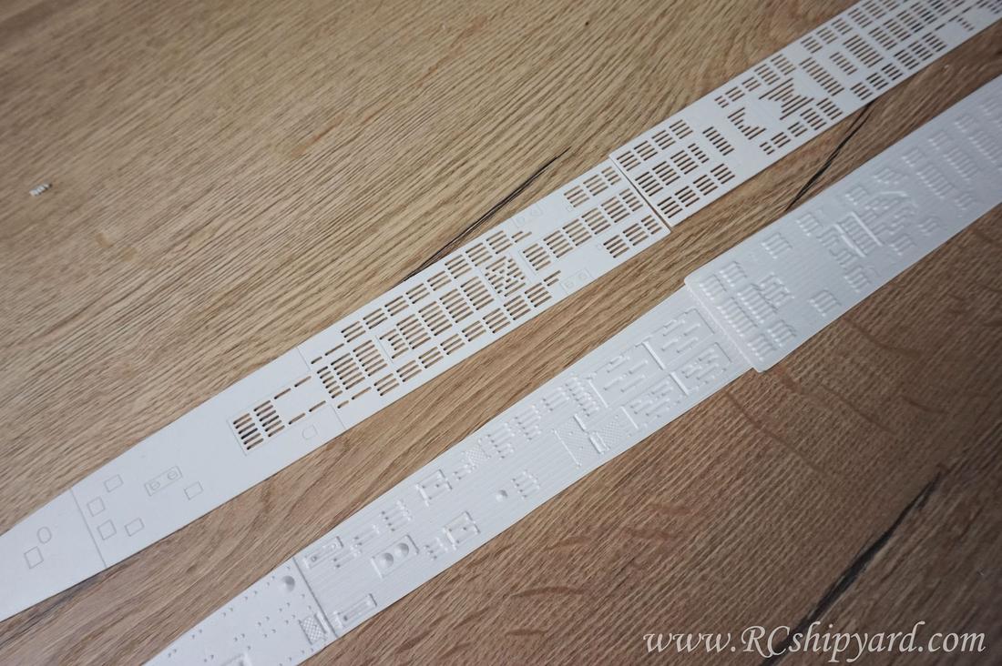
The slots are really tiny and quite historically correct. I think they might have been done with a 1mm end mill.
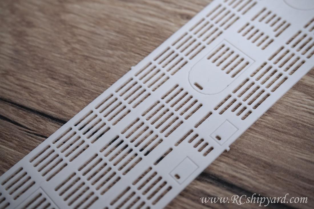
Quality difference is enormous, the after market decks are really better, yet they’ll require some extra work too. Sadly it’s quite easy to notice that one side of the decks has a rather rugged surface. Not a real problem, but at the price of 75 Euro the CAM program for the mill could have been made better.
While having decks with cut out slots I don’t have to worry about air getting trapped under the decks any more – a very important thing. But still I had to cut out the holes in the hull beneath the new decks. Some decks will be glued permanently to the hull while others will be magnetic and removable allowing to service the model flooded mechanics. The shape of the service hatches seems rather peculiar, right?
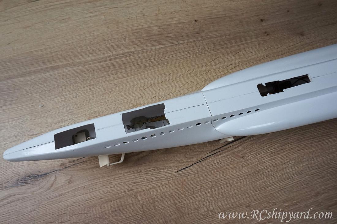
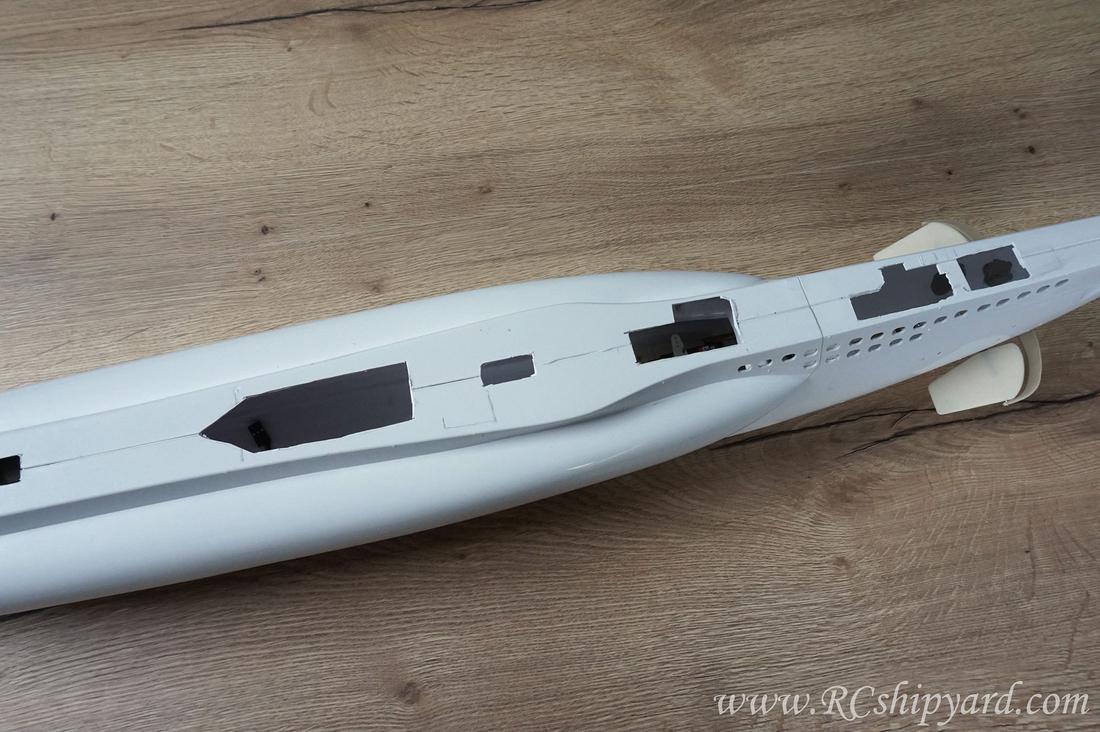
They’re in those weird shapes, cause I wanted to make sure I’ll not end up with a line of cut in the middle of the deck’s slots!
At this point this thing finally looks like a submarine, right? Just why that damn decks are to long if they’re dedicated for the 1:60 Krick!
10. Conning tower
Elements for the tower supplied by Krick since the beginning seemed really primitive to me. The effort required to make something not laughable from those would be enormous and the effect would still be moderate at best. They simply had to go. (Their course was towards the trash can obviously)
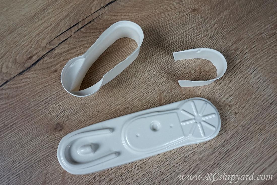
So of course my idea was to design it in the CAD software and then print it. Then, after the initial sanding adding some of the details like the ladder steps and emblems. As the tower of the VIIB is rather simple, it was a good time to try hitting two birds with the same stone and also test the capabilities of one of my 3d printers – the FDM Prusa MK3S. Normally I would print the rails as flat elements and then bend them over a heat source into the desired shape (As I normally do, what you will see further in this log). Yet, in this particular scenario even if it would be to much for the printer and the rails would end up as spaghetti, I would have simply cut them off and attach new ones made with my trusty old method.
While designing this tower I did look at many photos of the VIIB and VIIC towers on the internet and also at other 3d models already designed for 3d printing. I did copy some of the good ideas and sadly the bad ones too from folks whom already managed to design a decently correct tower for the VII type. On well, sadly that’s what you get when you look for inspiration from the internet rather then the history books.
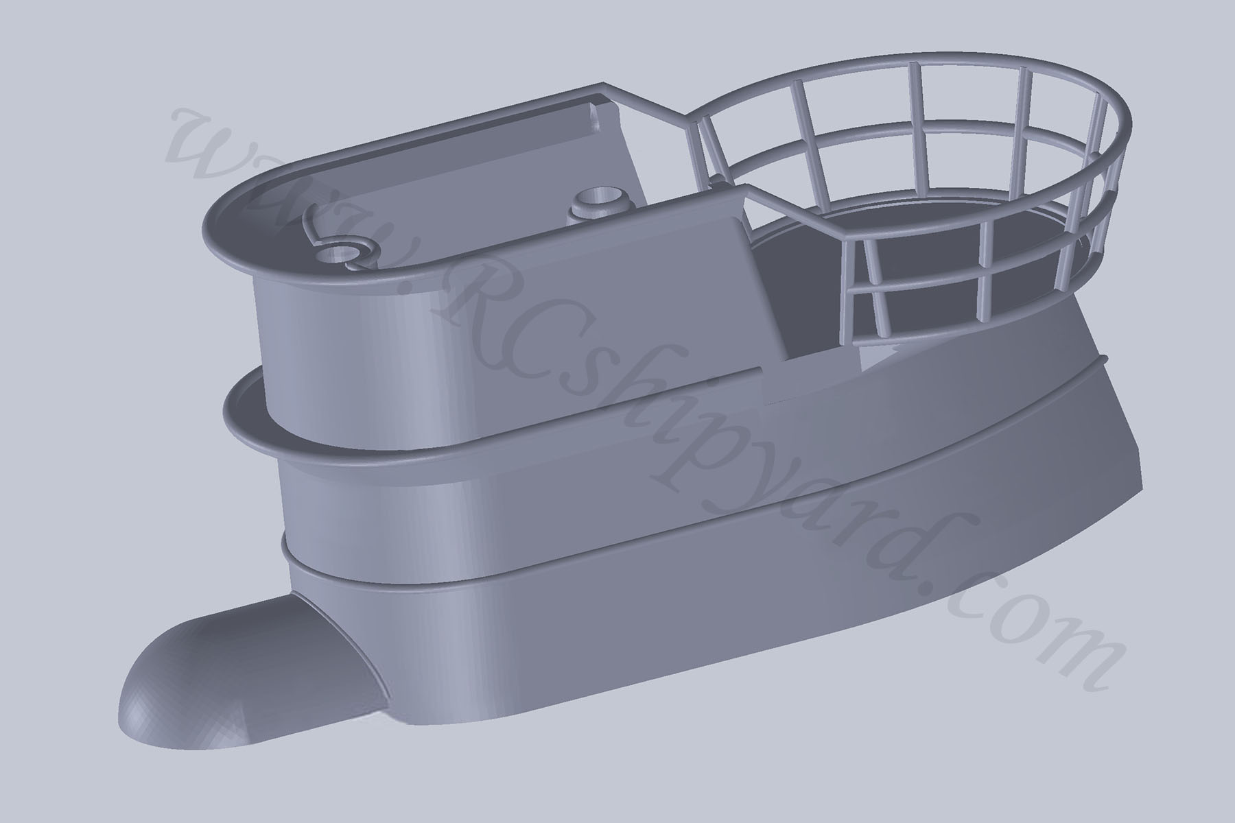
So, after few more changes in design, the final model ended up looking like this:
Further work on some of the details getting attached: the emblem and the decks which I had to cut in two and then cut their sizes down by hand to make them fit my tower. I still need to do some flooding holes and/or vents and service hatches.
In the end the decks fit, still they’ll require some sanding, but I’m sure that in the final stage they’ll fit in nice and snugly. It’s worth noticing that even when using such technology as 3d printing, you’ll get a better effect when using several separate elements rather than printing everything at once. Some exceptions apply to the liquid resin printers, but I had my resin printer busy at the time when this tower was designed and as I said before – the rails printed without the supports were a big experiment for me – as a user mostly of a “classic” FDM printers, but the Prusa MK3S managed to make those quite decently. Some of them look “bendy” and maybe their lower edge will require some sanding or corrections with a heat air stations, but in the end I’m very pleased with both the design – at least compared to the Krick elements and the printer “torture test”.
This is how the tower will look on the hull. Of course just placed there for the moment as it will be finished and painted as a separate element. But before the paint work it’s time to deal with that ugly flat hull.
Less Krick in my own Krick with each step, right?
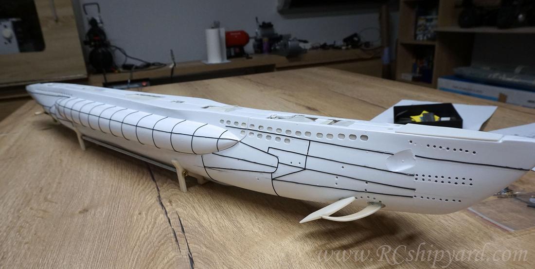
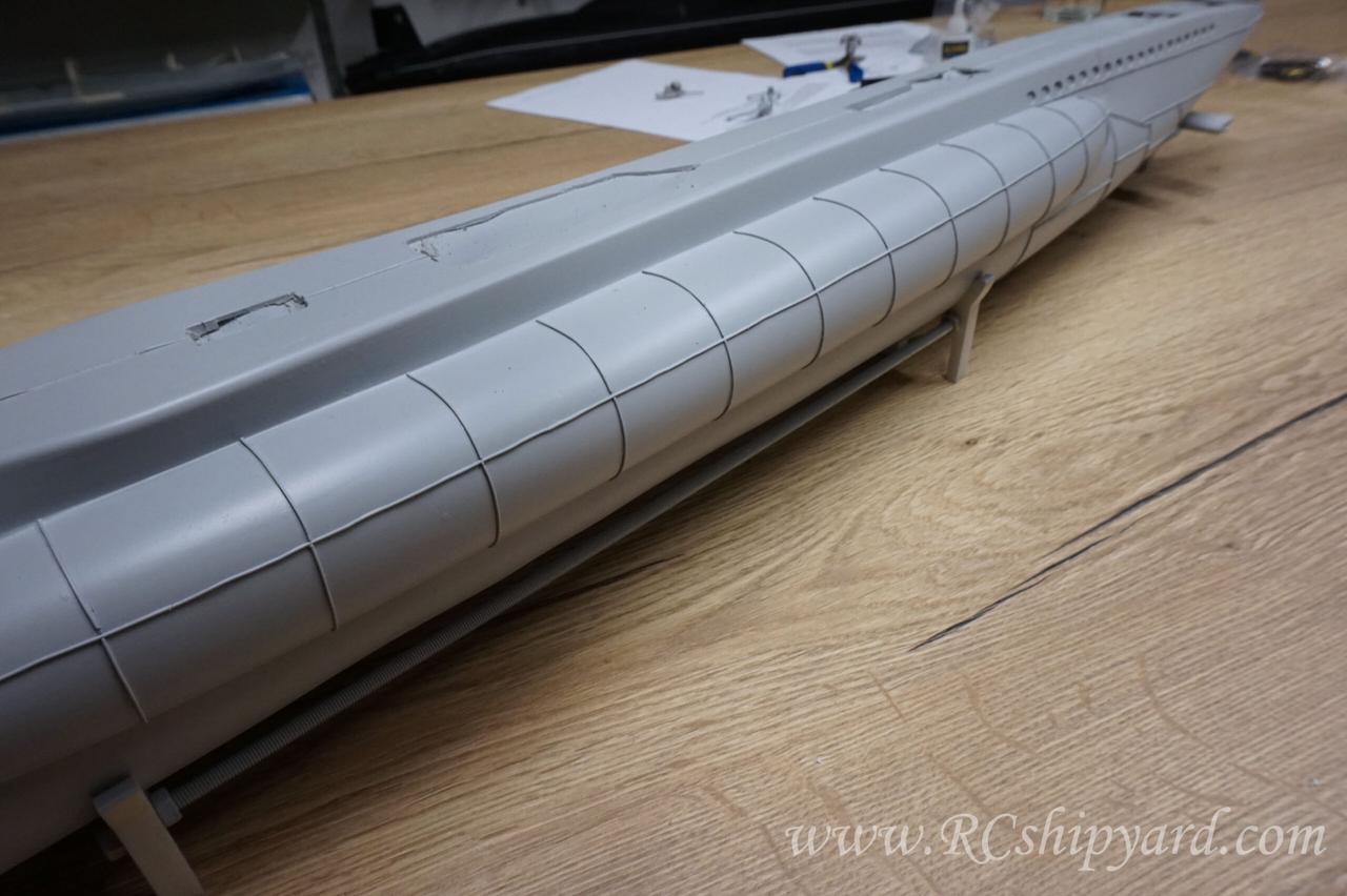
11. Hull details – part 1: welds
I really don’t like the flat surface hulls, so I had to do something with the Krick’s hull:
A pen with a ruler, cyanoacrylate glue and lots of Kynar wire…
After few hours of work starboard was finished (left photo). Few more hours and the port side was finished too (right photo).
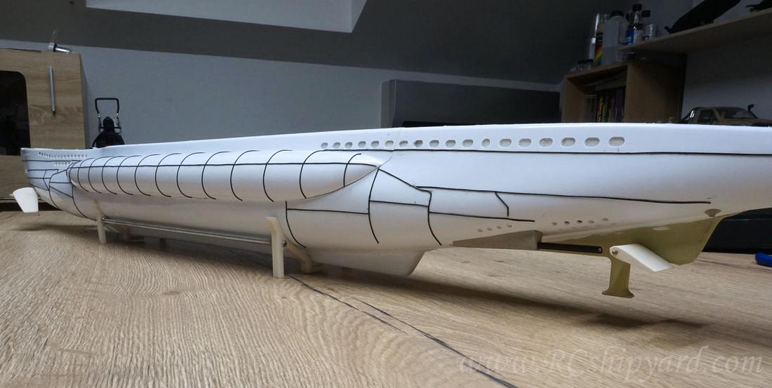
Top view, with the way to wide and bulky saddle tanks. I already saw that some of the model makers have modified those and it does make a great difference, but I decided that I’ll leave them as they are. Partially from being lazy and partially to leave at least some of the Krick’s spirit in this model…
12. Painting – part 1: primer/undercoat
The weather was kind enough to let me coat the model with a few layers of spray primer. The darker spots on the hull are shadows from a big old larch which grows on my land. The paint has been distributed evenly and I managed to cover every detail and nook.
The decks, tower and few of the other smaller details have been covered with the primer too.
Inspecting the hull’s paintwork in my workshop. My initial thoughts are, that finally it’s not looking like a cheap ABS made toy.
Now I’ll leave it for a few days to dry completely and do some work on the details which I’ll need to assemble or design. Depending on the one quality of those delivered with the KIT.
After the initial drying I did inspect the decks too as they were more prone to painting defects. The spray primer is “Tamiya super fine”. Till now I was using mostly the “Chaos black” primer, but sadly they most likely changed something in their paint’s composition, as since a while it’s a worse and not really worth the money any more. Of course that’s my private opinion.
13. Painting – part 2: base colours.
So first I had to paint the “under decks” in black, it will give the grey deck a better visual 3 dimensional structure. Also the black colour will mask the places where deck wasn’t cut. It’s a bit of an illusion – I’ve once read about that in some book about movie effects (from the 1990s) and I want to try it.
A little cameo in my own building thread thanks to my wife and her trusty IPhone. Of course I’m applying the grey colour. Loooot’s of it. 2x 23ml Tamiya jars have just left the building.
Flat grey finally applied…
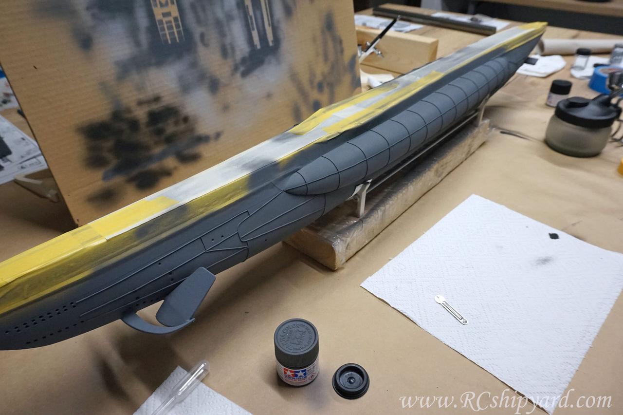
…and some initial shading. I do shading by mixing the final colour with some black colour, additionally reducing the airbrush pressure. Works wonderfully for me!
Removing the old tape and applying new one – to cover the job already done. This is how it looks when getting ready to apply the last base colour:
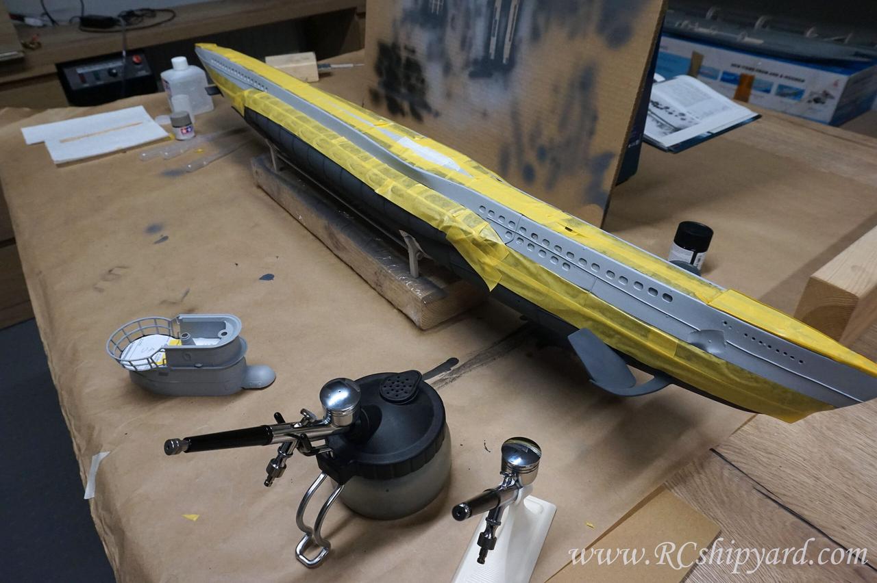
The same black “under deck” technique was applied to the tower’s deck too, so it had to be masked before applying the base grey colour.
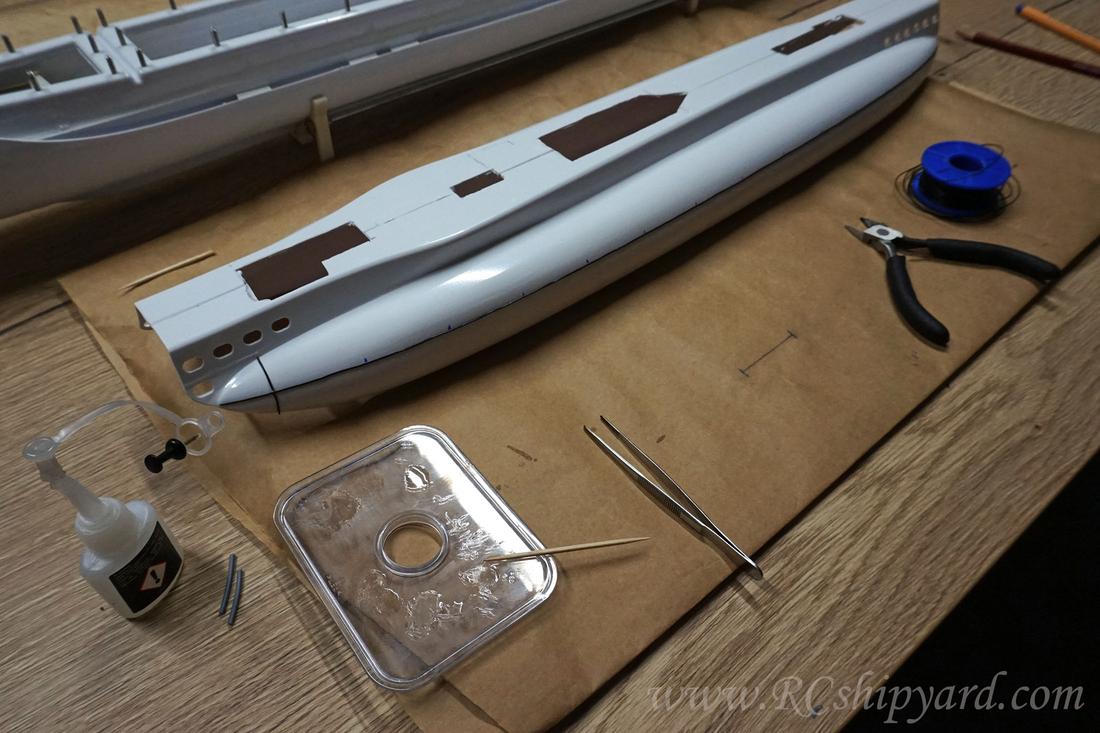
14. Hull details – part 2: deck details.
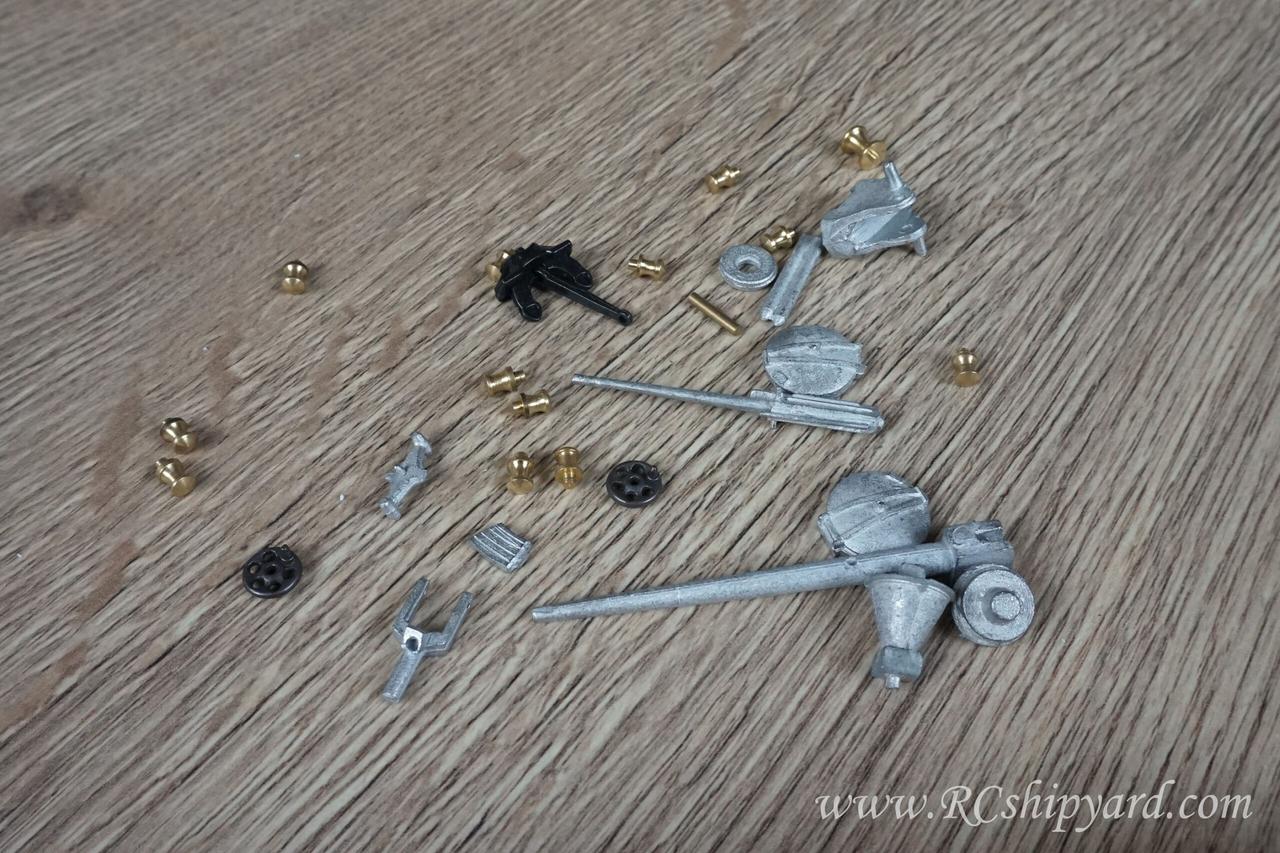
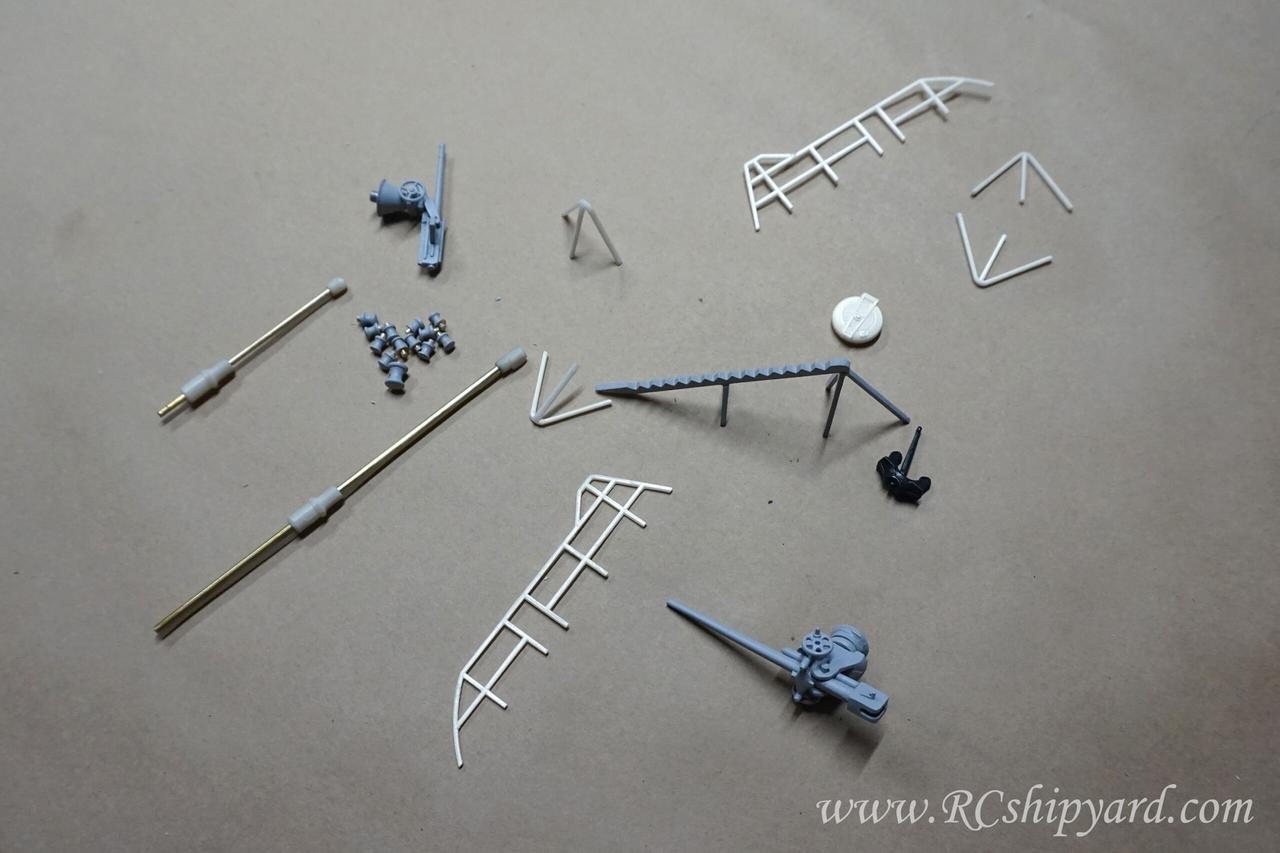
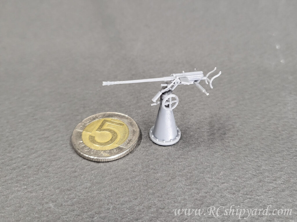
Krick has included some details made from lead. They seem nice, require lots of sanding for sure, but I’ll use them. Still lot’s of other details characteristic to type VII are missing. Especially the rails and the periscopes.
Left picture: Parts not supplied by Krick are not a big deal to me, as I can always to design the missing details. In the lower left you can see the observation periscope, still need to design the the attack periscope, which will also hide the snorkel for the ballast system.
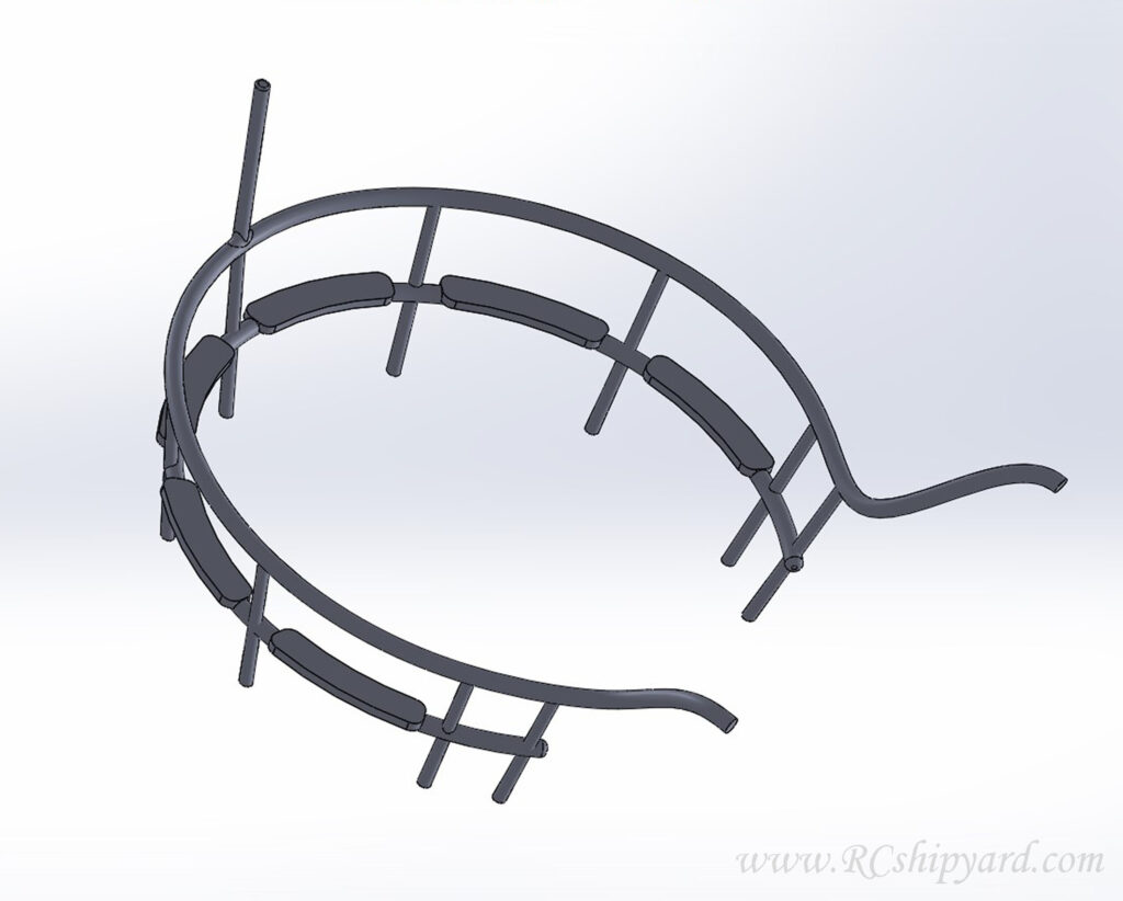
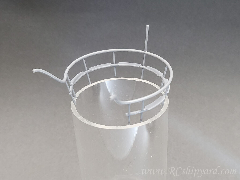
Right picture: And of course the missing rail – the one around the deck gun. It will be 3d printed as semicircle flat object – with a mirror of itself copy. Then the plan was to glue them together to make a round railing and shape it over a heat source to a correct shape of the hull. so to make two of the rails I’ll need 4 such elements.
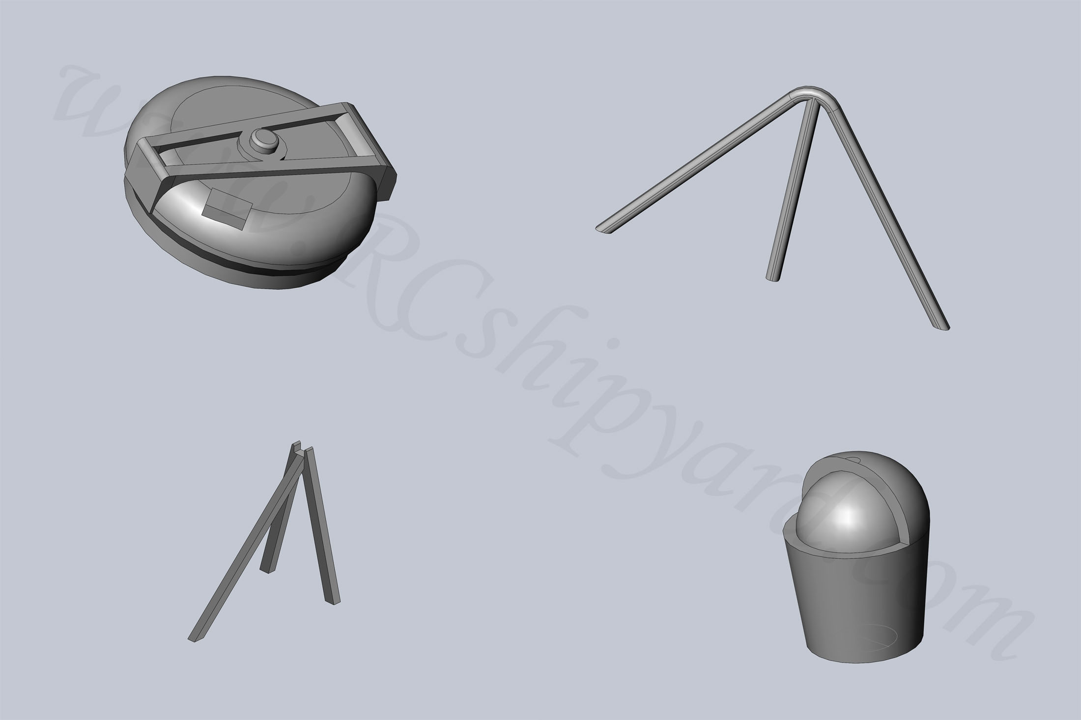
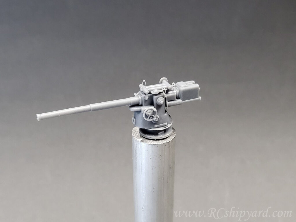
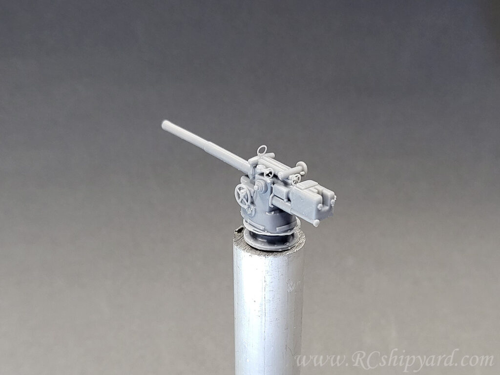
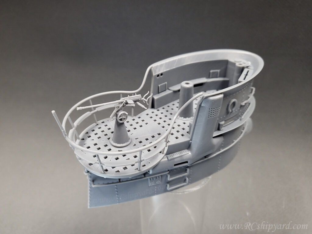
Another photo of the details. The deck gun, the flack gun and the net cutter which were supplied by Krick are already assembled and covered with a layer of primer. My 3d printed details are still waiting for their turn.
The additional details for this model can downloaded from HERE
After taking the masking tape off I was fairly happy with the result. I’ve also applied the first weathering shadows right away after the main paint. It’s essential for me to do it right away as I make my shadows by mixing the base colours with 10-20% of black colour, so I need to use the exactly same base colours (colour – thinner ratio). Still, the deck gun and the flak gun are only covered with primer and require further work. But they will be painted with slightly different paint than the deck.
Bow view:
Stern view:
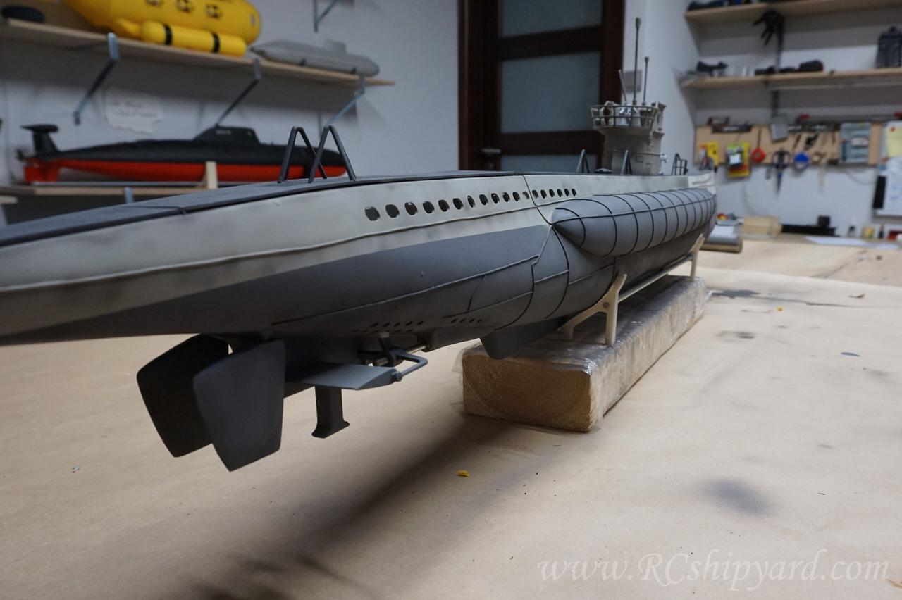
Rudders and dive plane stabilizers have been painted separately. They’ve now rejoined the hull. The stabilizers had to be fixed in place with some epoxy, it’s joint (little grey are above the shaft) will be painted at a later stage.
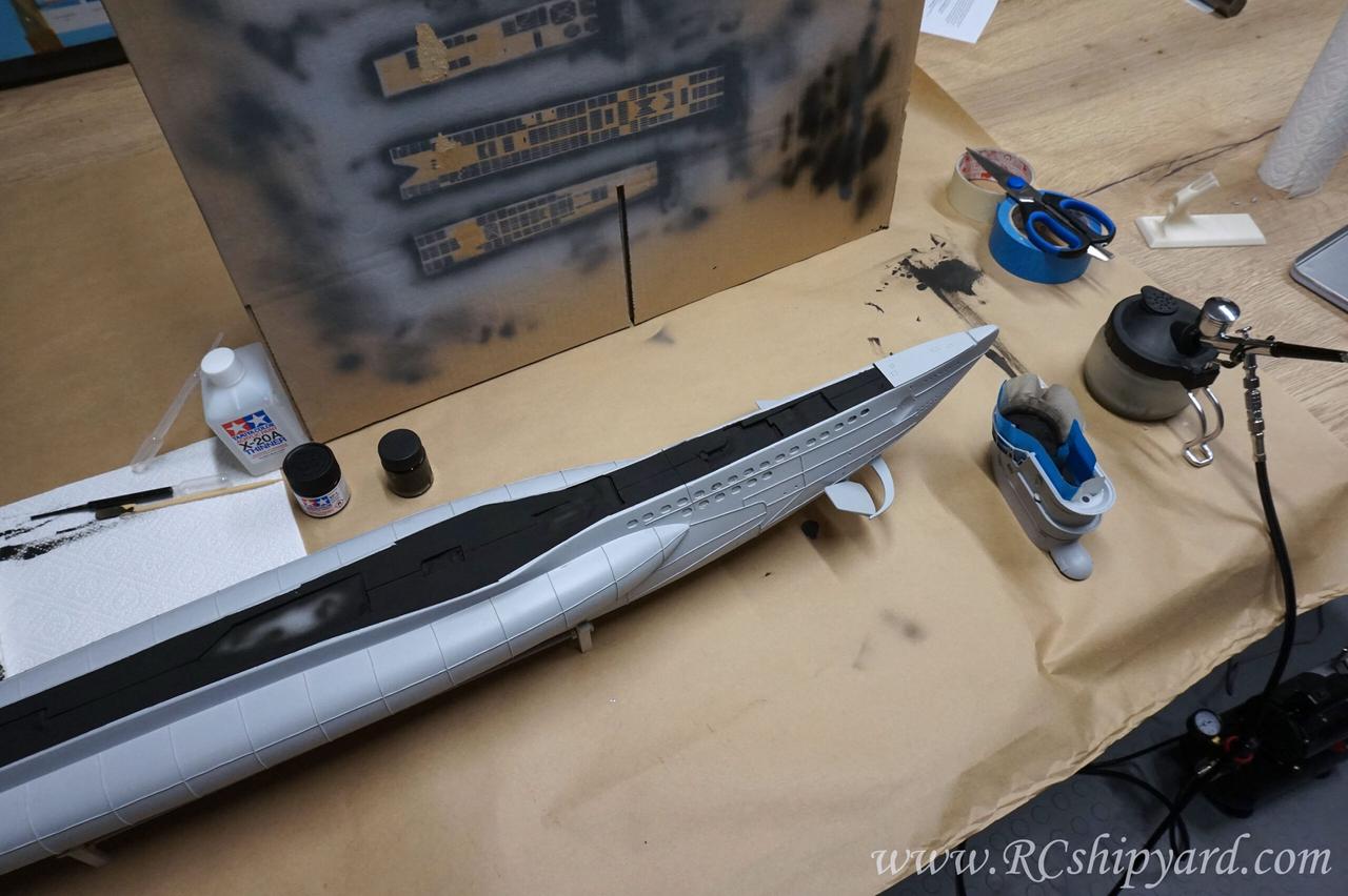
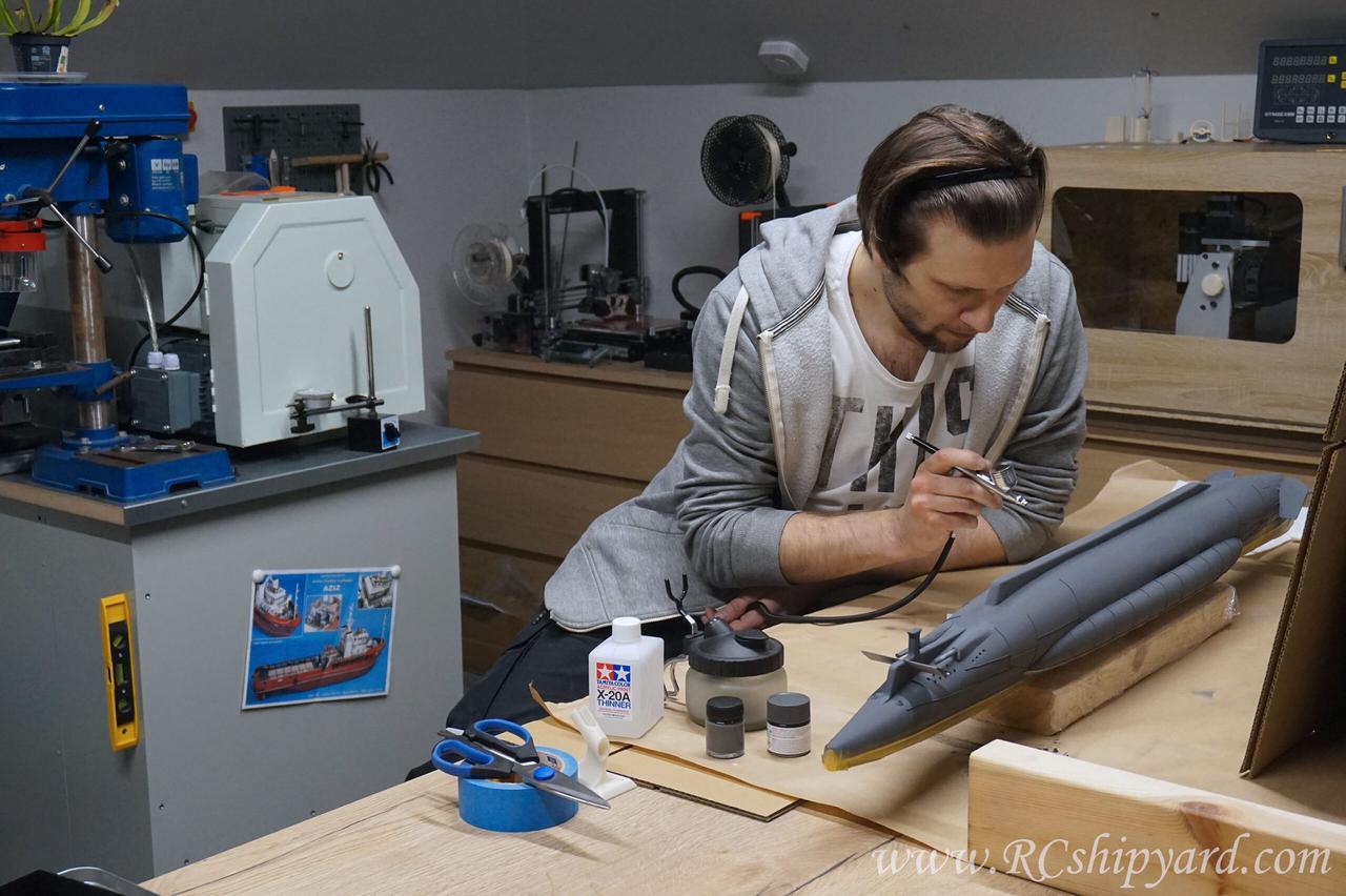
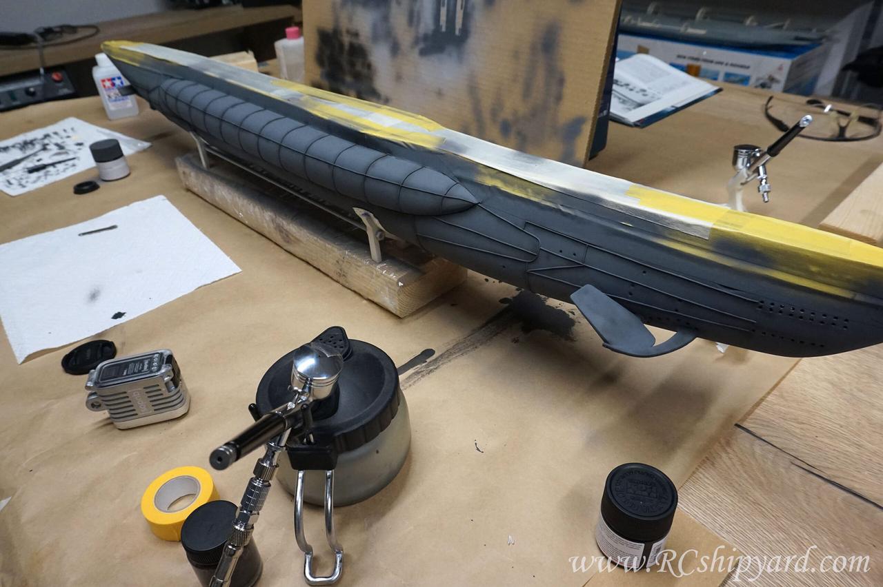
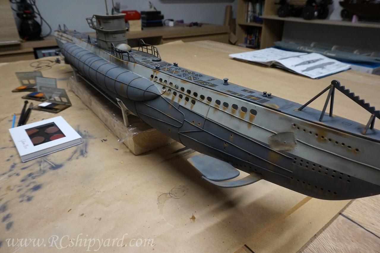
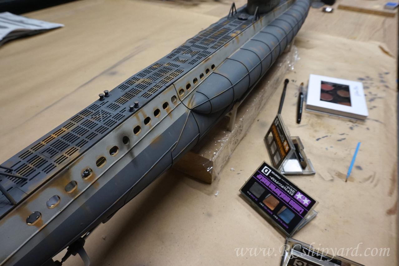
15. Painting – part 3: Weathering
I use mainly Tamiya products so when choosing the weathering KITs it was obvious to choose their products too. Additionally I have used some human make up KITs as I wanted few additional rust colours. I apply them all by a little sponge with a rounded top.
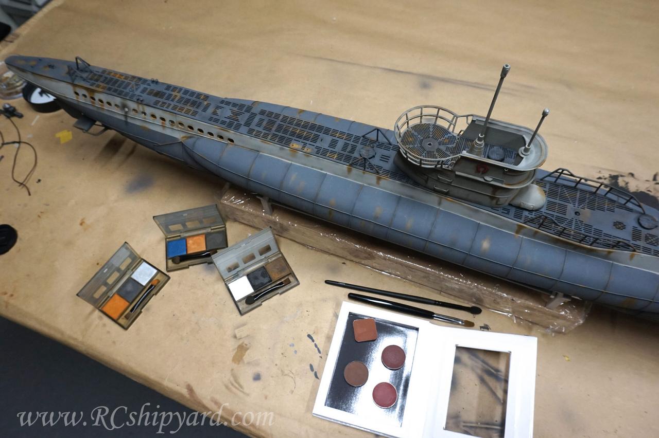
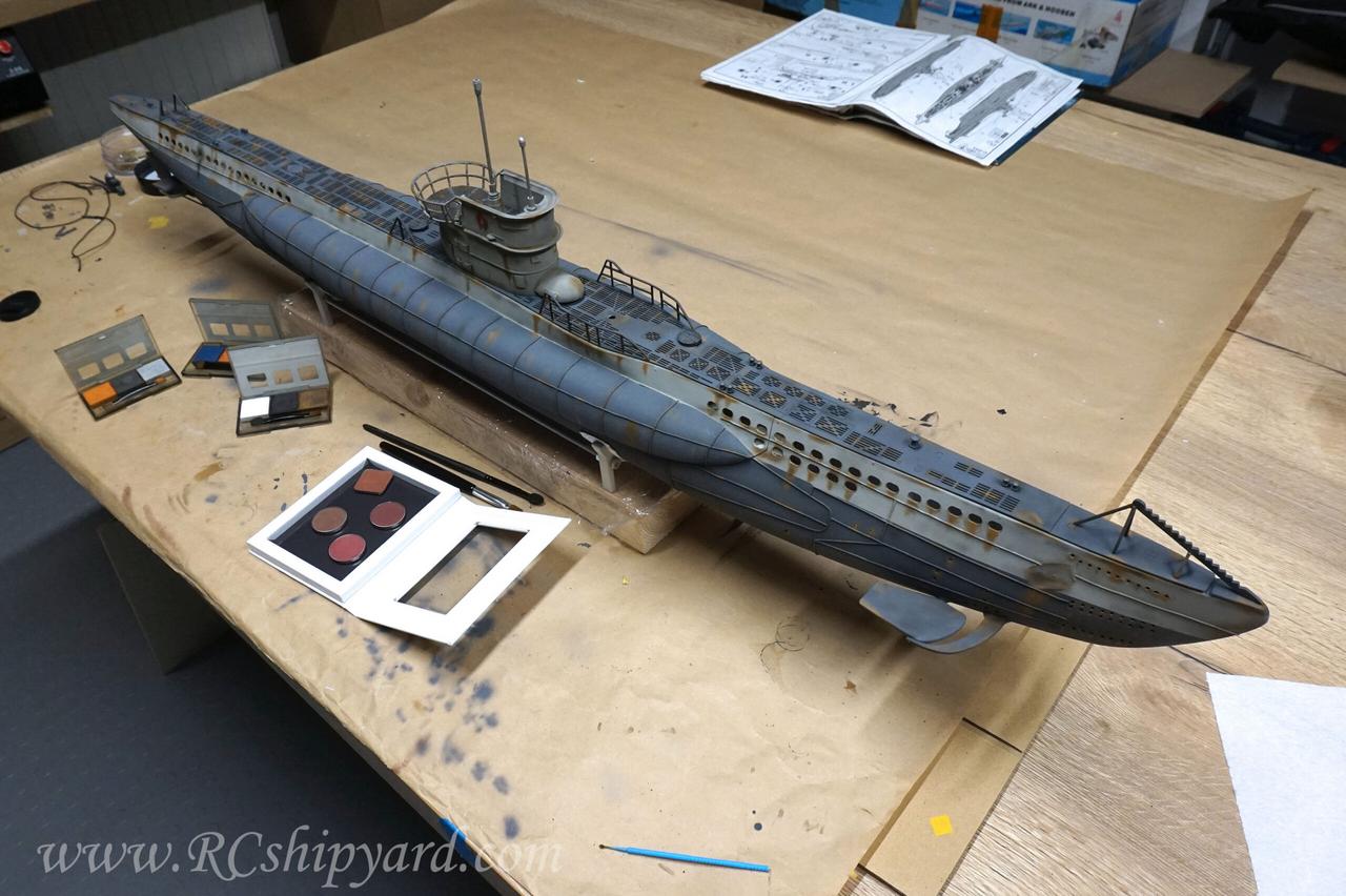
As the model will have contact with water, all the weathering will have to be covered with a thick layer of varnish. This will tone down all the weathering colours so it’s worth to remember to make the weathering a bit more bright and vivid at this stage of the work.
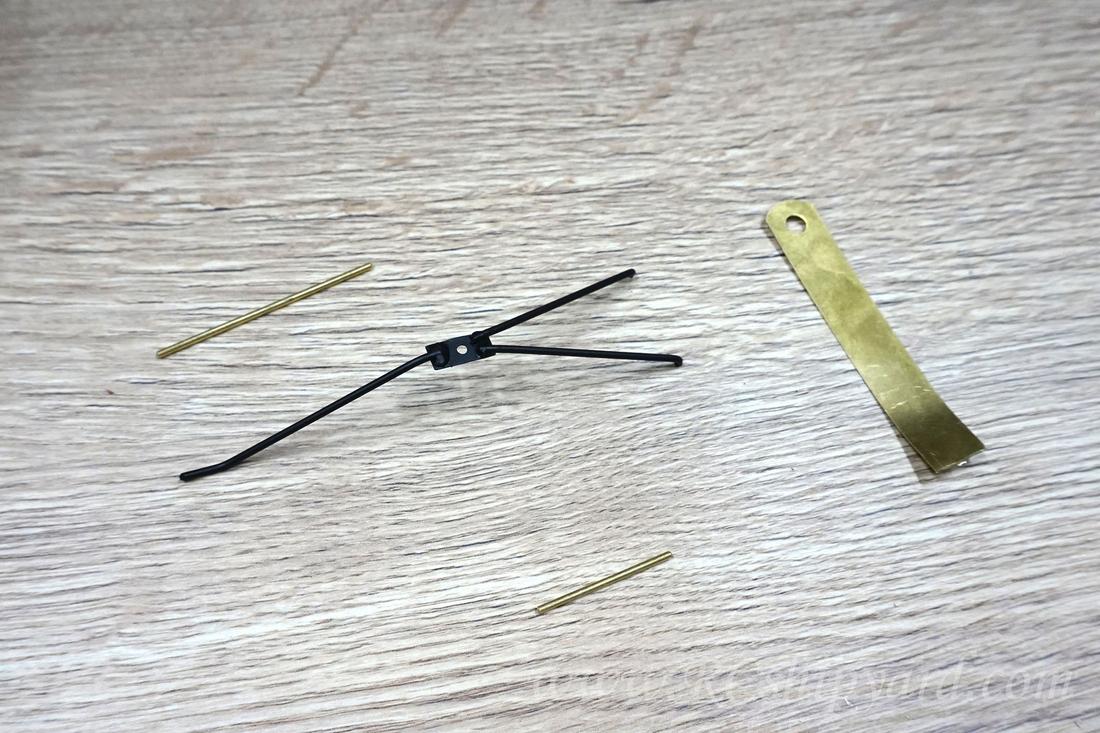
16. Hull details – part 3: lines and rudder stabilizer.
At this point I have also made other missing details – line tensioners ( I believe that this was their function).
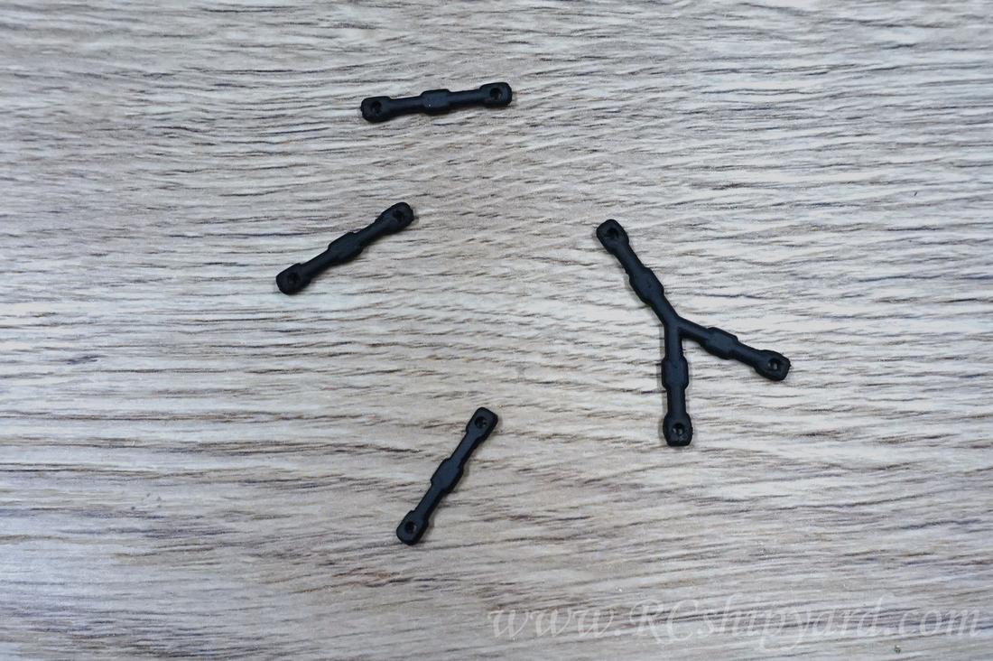
The last missing details were the rudder stabilizers/protectors. I’ve decided to made them out of brass and solder them manually, instead of a 3d print, as this element may easily hit the bottom of the pond.
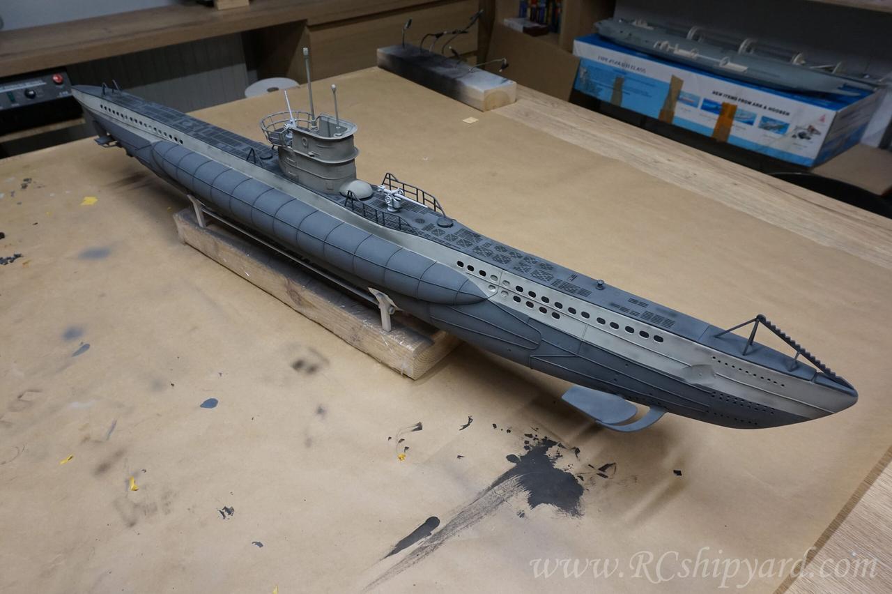
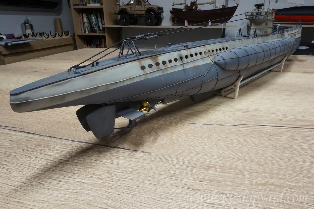
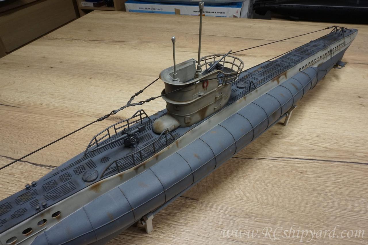
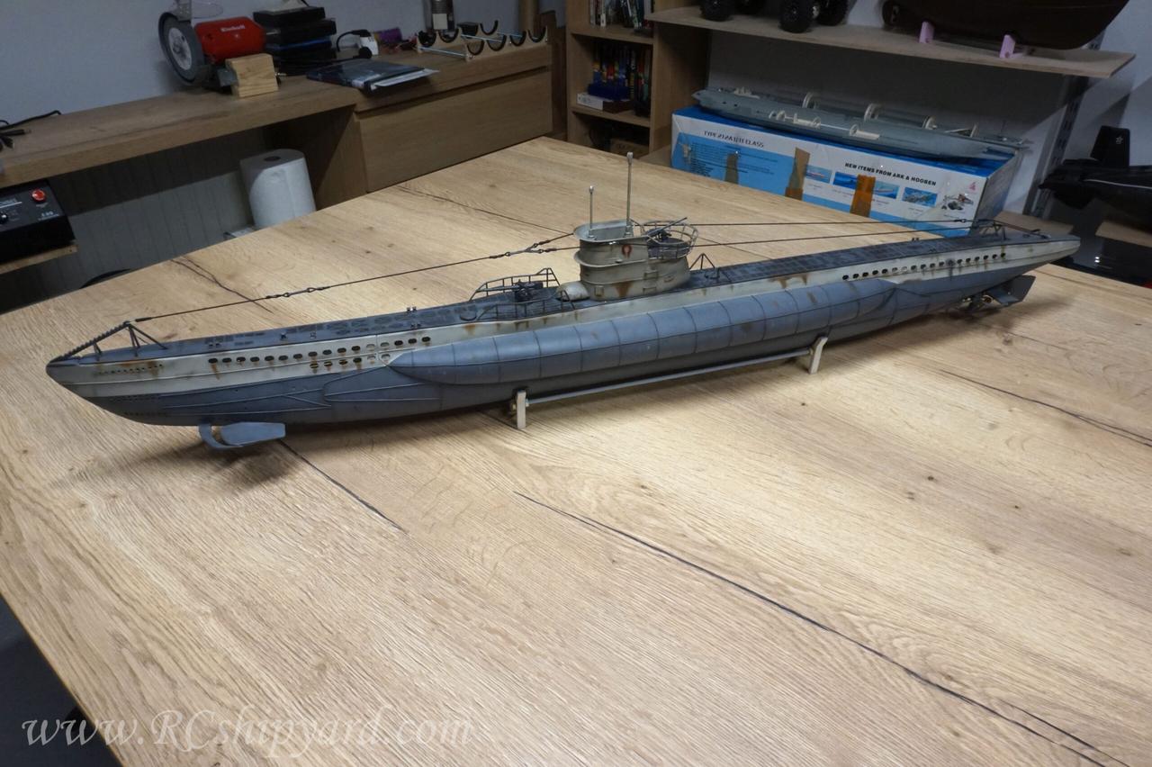
17. The hull has been finished!
And finally putting everything together – adding the missing guns, lines between the net cutter and the tower and of course….
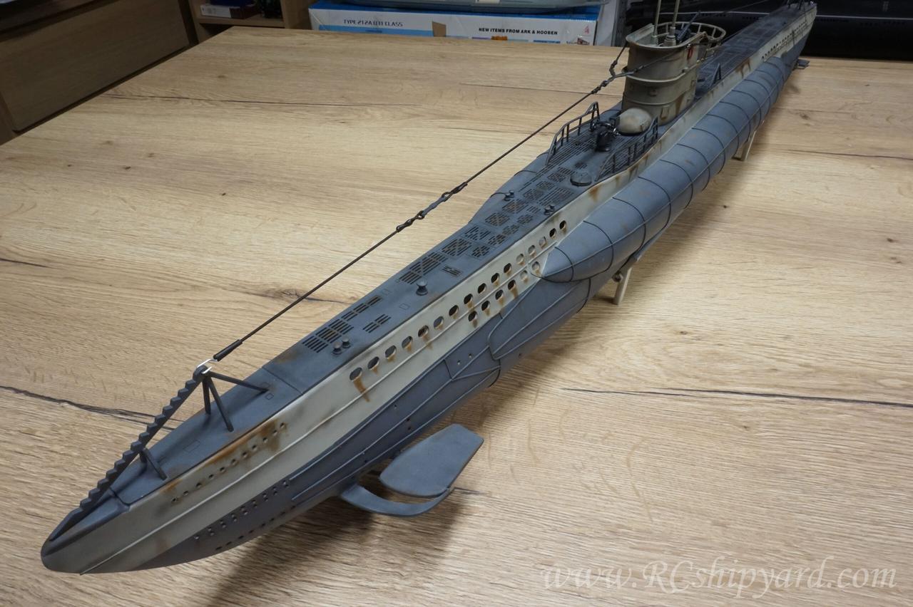
…the complicated rudder system with all those connectors and stabilizers.
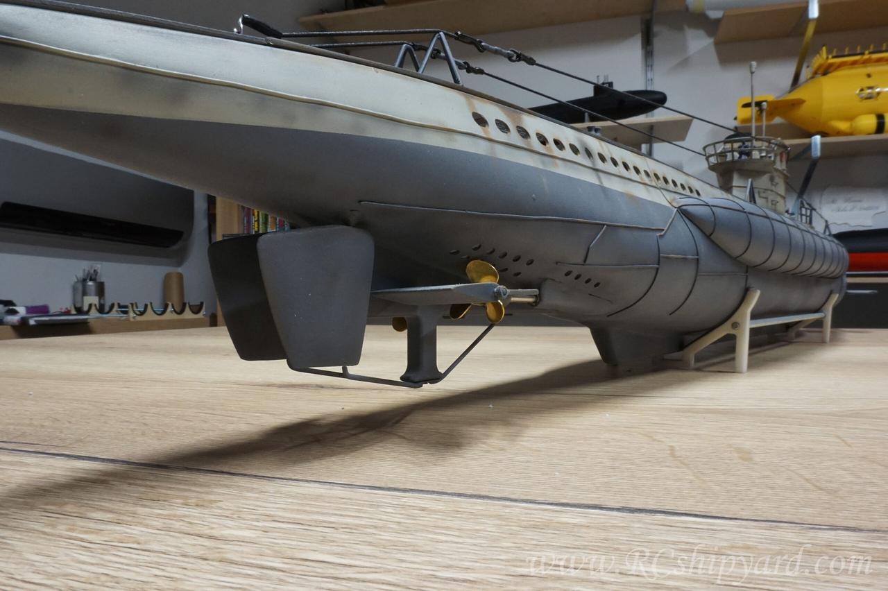
Stern lines
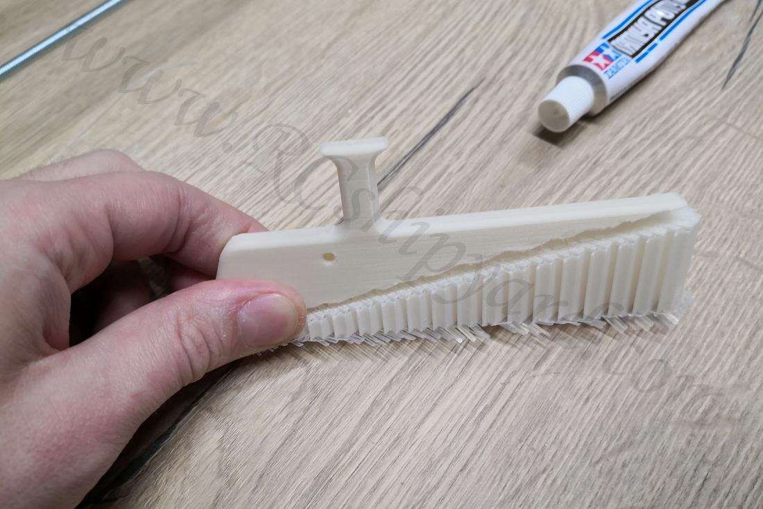
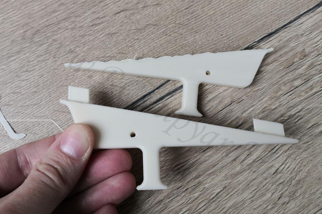
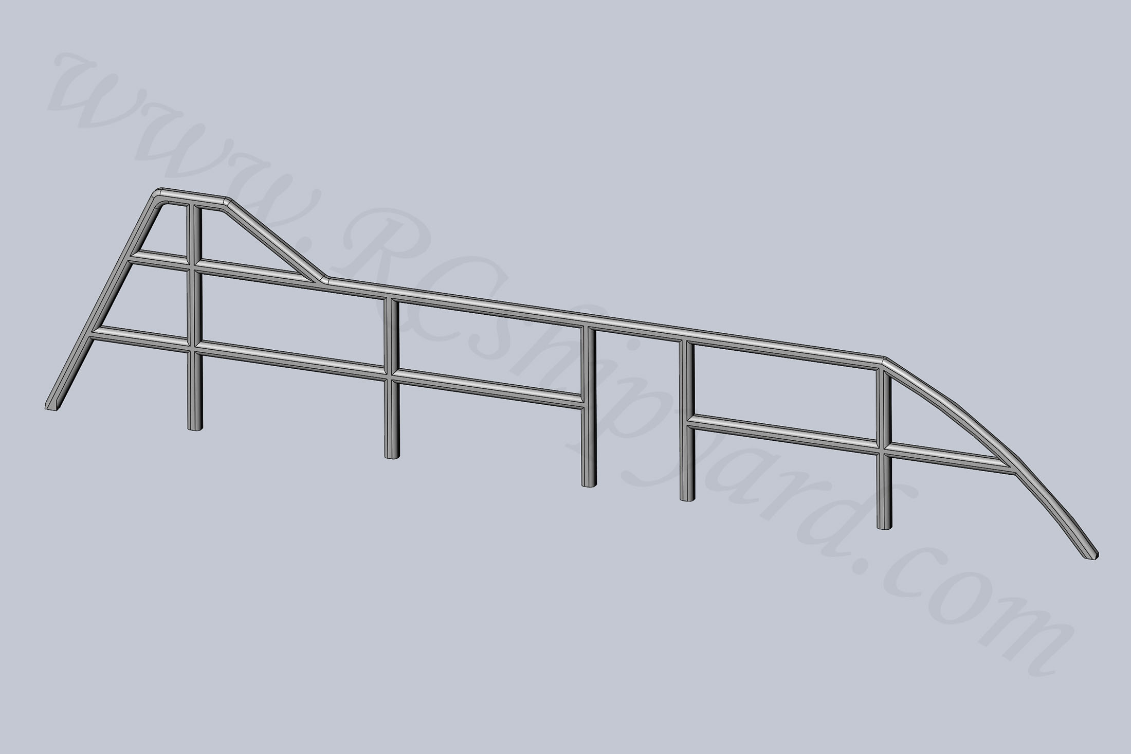
I’m extremely happy with the end result of the railing around the deck gun, as it was a big experiment to print those flat as two hemispherical elements each (each railing – four elements in total) and then gluing them together.
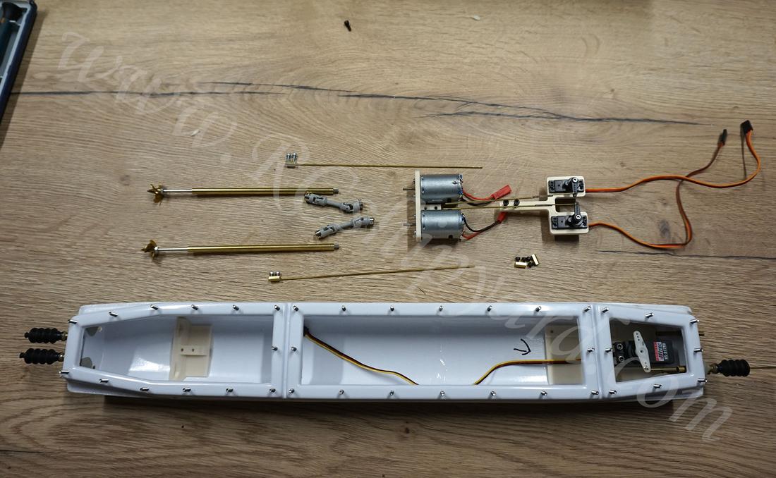
At this stage I consider the model exterior as finished and I’ll be moving to the missing internal systems.
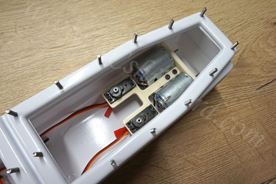
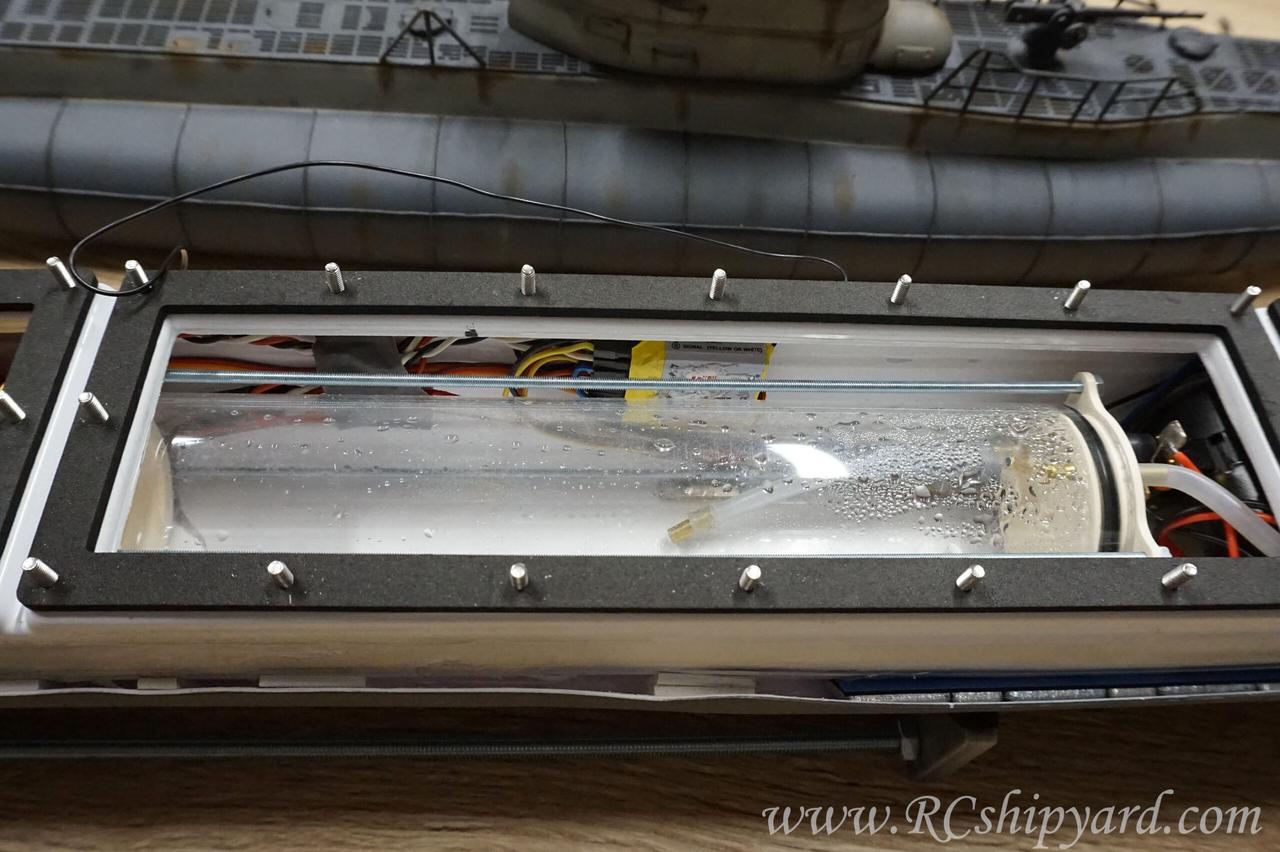
18. Internal systems: RC, diving system, battery pack.
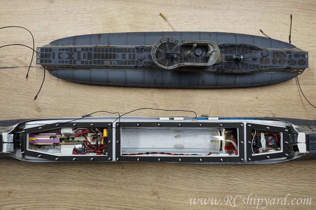
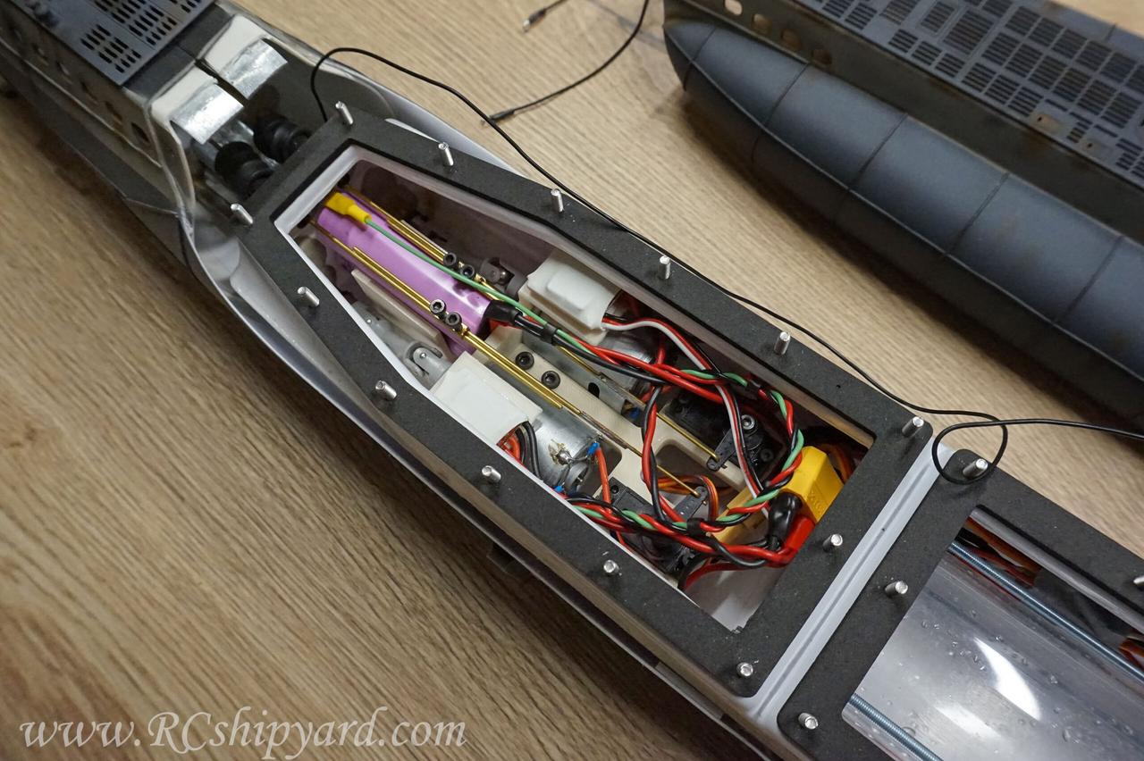
Stern of the WTC is the engineering section of the model housing crucial RC elements to run and control the model. Most of the place here is consumed by the motor block described earlier. My VIIB has two independently controlled brushed electric motors – each with it’s own ESC. Motors are connected with the shafts with a double cardan joints. Between the two cardan joints you can see the Li-Ion battery pack consisting of two Samsung 3500mAh 20A cells. These are excellent cells with technology allowing to charge them up to 4.2V per cell, instead of normal Li-Ion cells which have a voltage of 4.1V per cells (fully charged). Stern diving planes and rudders are controlled by two Corona micro servos.
Middle section houses the enormous ballast tank (357 ml) and the RC receiver. I found this place as an optimal location for the receiver as it’s the furthest location from the ESC, motors and the pump and as we all know – these are the biggest electronic noise generators in a model and they can cut your RC range significantly.
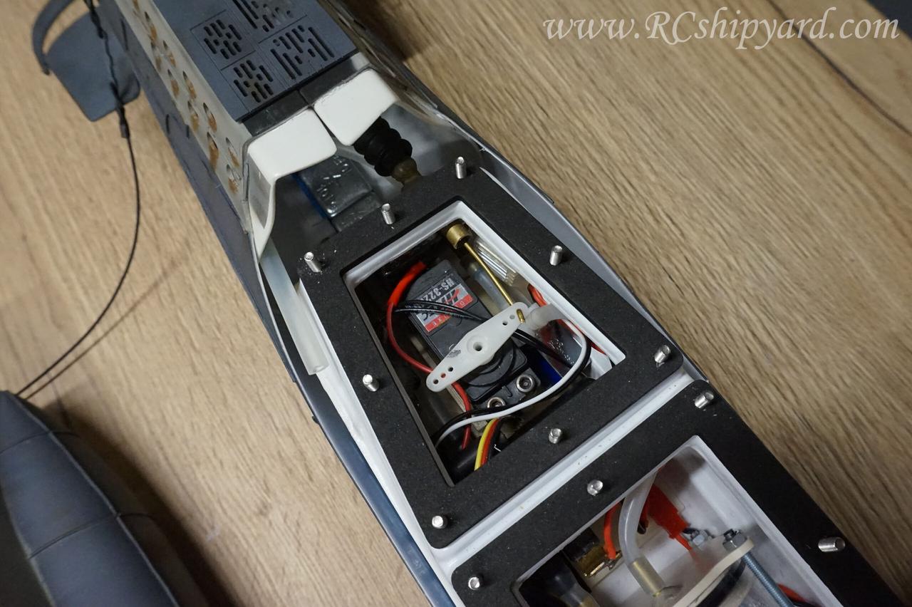
Bow section of the WTC hosing the bow dive planes servo, pump for the ballast tank, ESC for the ballast tank, electric solenoid and the Arduino controlling the solenoid. This things are barely visible here as the opening in the front is narrow and offers limited access. Using a standard servo was totally unnecessary and I consider it as an error as it only takes up precious space.
19. Ballast system in the VIIB – how it works.
The VIIB has a vented ballast tank system with a solenoid controlled by an Arduino. I’ve made a video explaining how a vented ballast tank works and how to make one if you don’t have a solenoid or skills to make one.
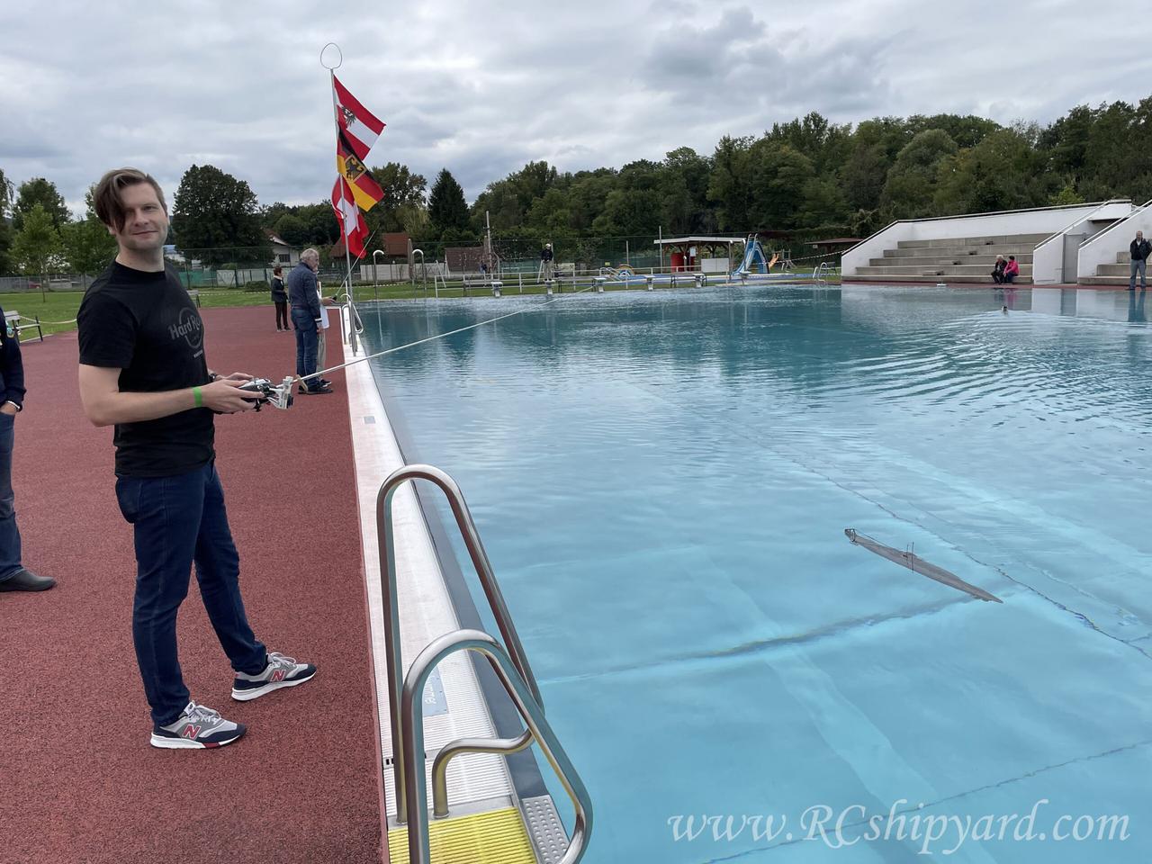
20. Maiden voyage
The trim which I have made in the tub earlier was not bad, I only had to redistribute about 5-10 grams of weight.
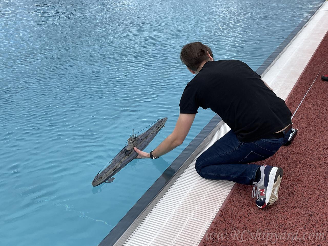
A quick surface run to check is the propulsion and steering working correctly…
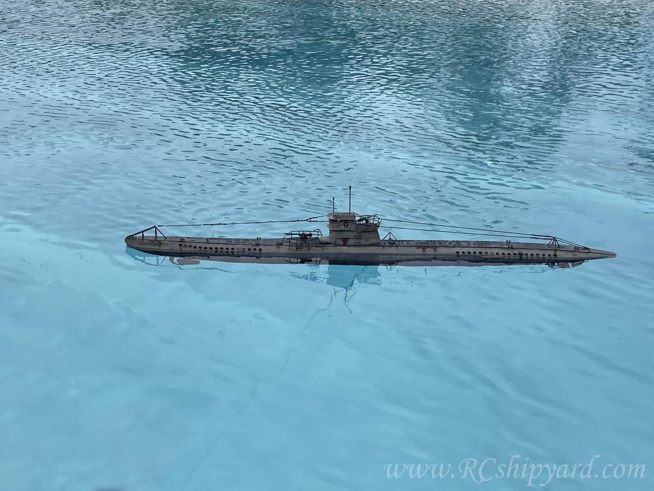
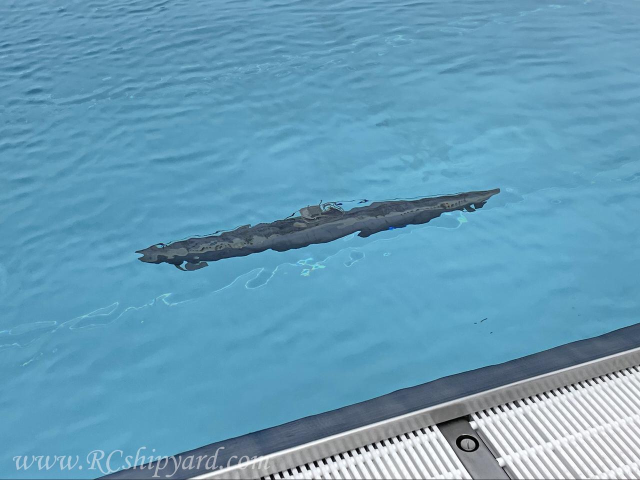
…and of course the first dive.
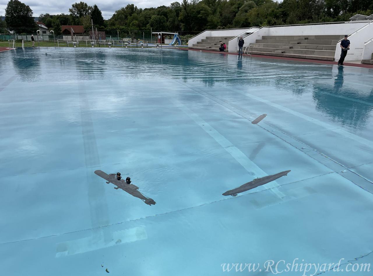
Due to a traffic jam I was forced to go below 1.5meter (about 6 feet) on a first run, but well – we all do it for that little chill!
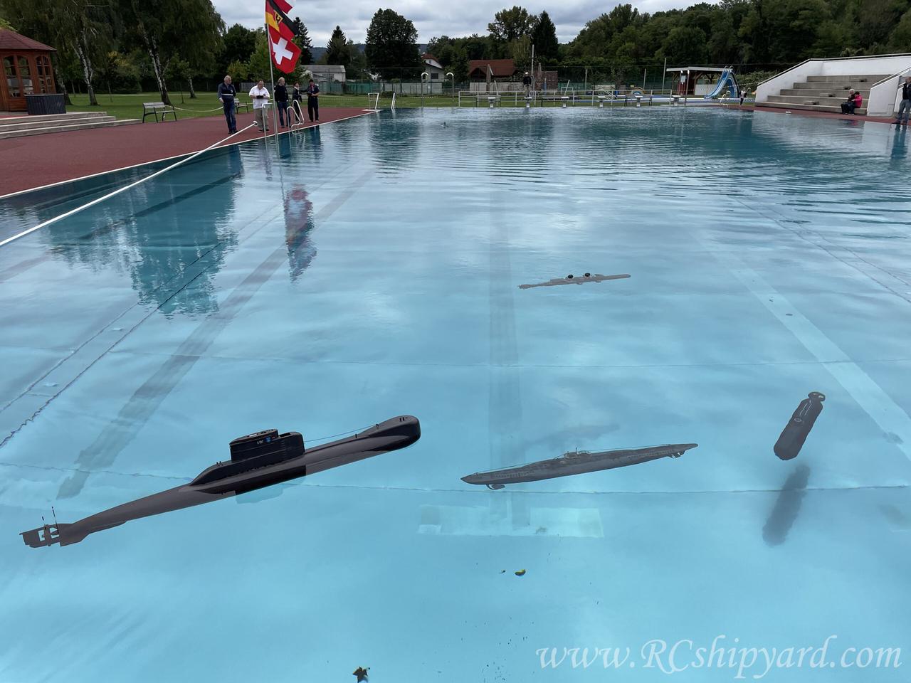
Surfacing the boat on full stop:
Only to get immediately attacked by the British!
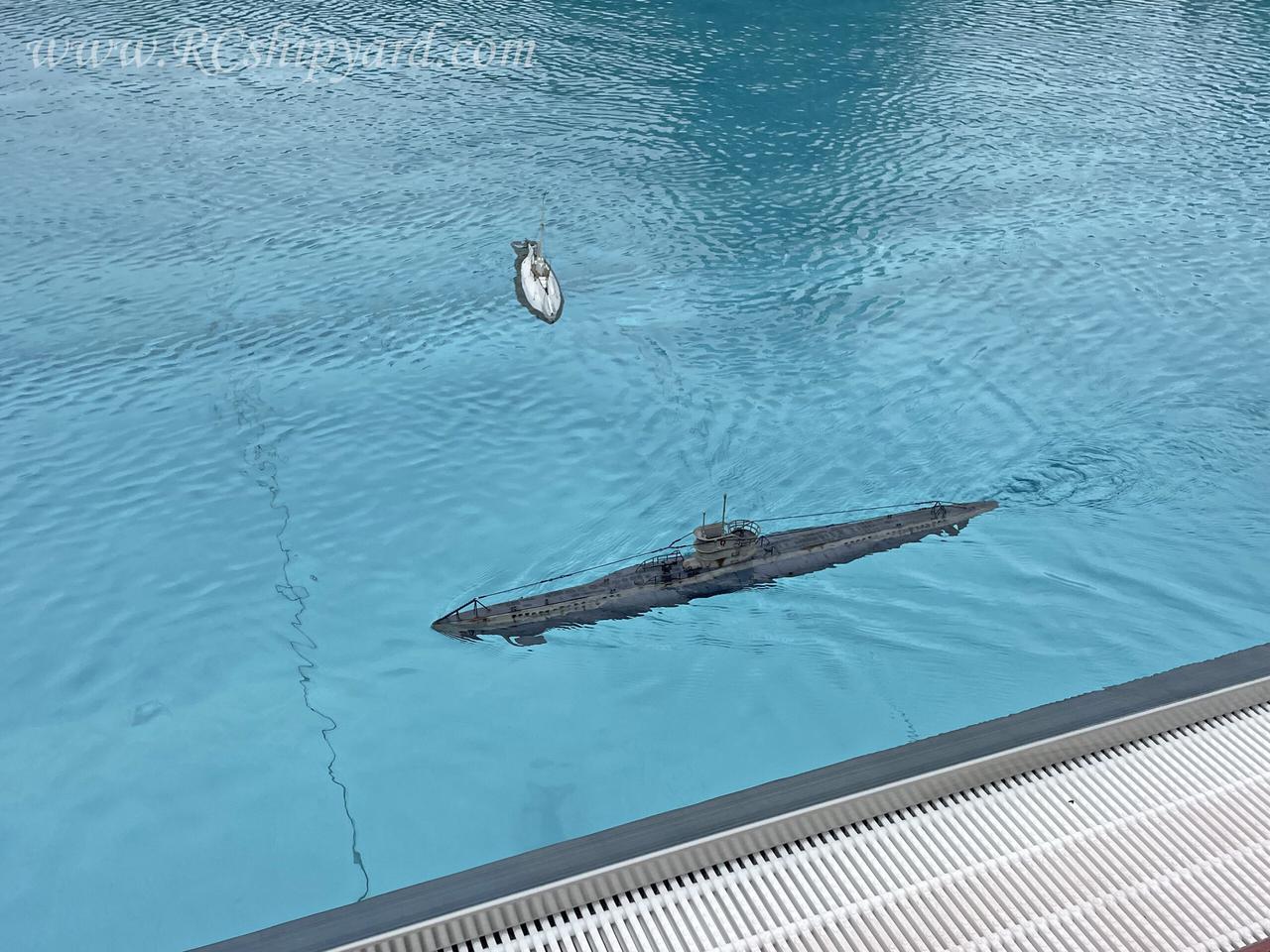
Luckily two props are better than one and the captain has successfully evaded the enemy with a swift surface maneuver!
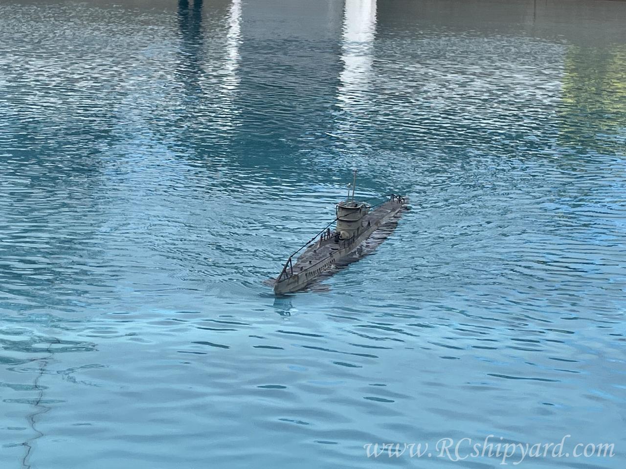
Still, underwater you will always find someone who is faster than you, those d*mn subs from the XXI century!
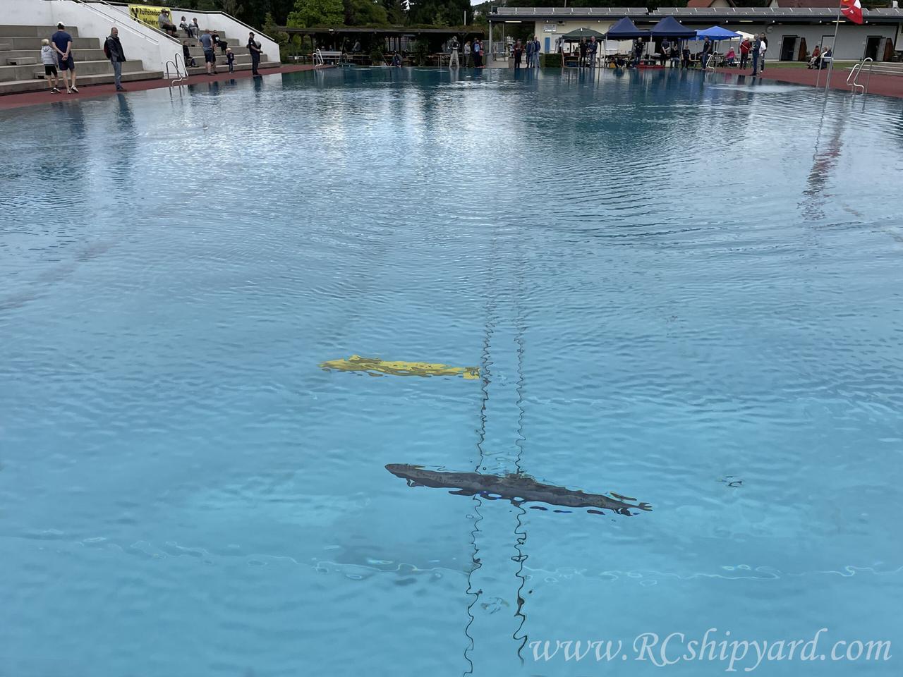
And of course a captain’s happy face says it all 🙂
21. Some final words and thoughts.
So what can I say about this KIT…
In my opinion Krick should include a formal apology in every box with this KIT, together with a money return of about 60% of it’s value!
Rather harsh personal statement right? Still, I think I’m a person capable and skilful enough to make such opinion, as you can compare the Kricks idea of the model and my final effect quite easily.
Even as this was a rather fast built, I find the quality of this set from “terrible” to “moderate” at best. It takes enormous effort to achieve a decent looking model. To be honest, I think it’s not possible without the 3d printer and redesigning some of the elements. Because not everyone has 3d designing skills, but many people already have 3d printers I have included all the STL files in this thread. The biggest enemy of this KIT is the manual and the plans – treat it inly as a general description, as there are lots of errors and vague descriptions in both.
The model is operational since 18th of September 2021.
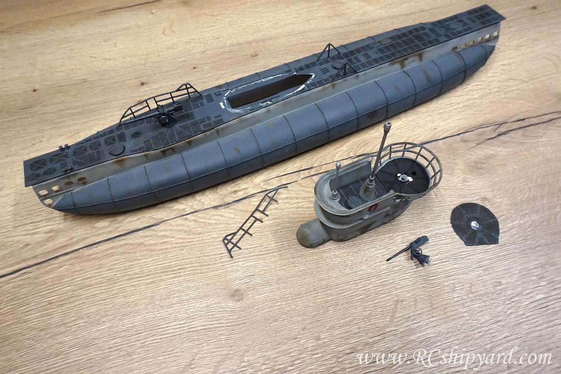
22. Modifications and repairs.
January 2023:
Sadly, the model got damaged during transport from the Submarine Model Makers meeting held on September 2022 in Bratislava:
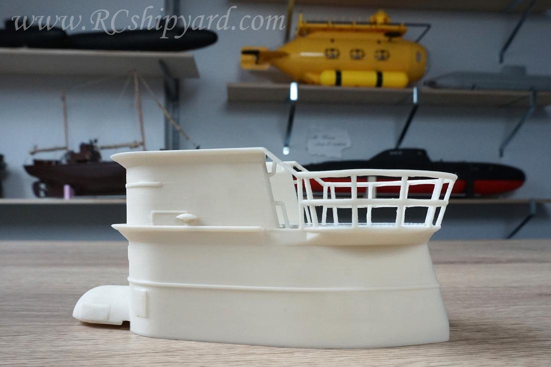
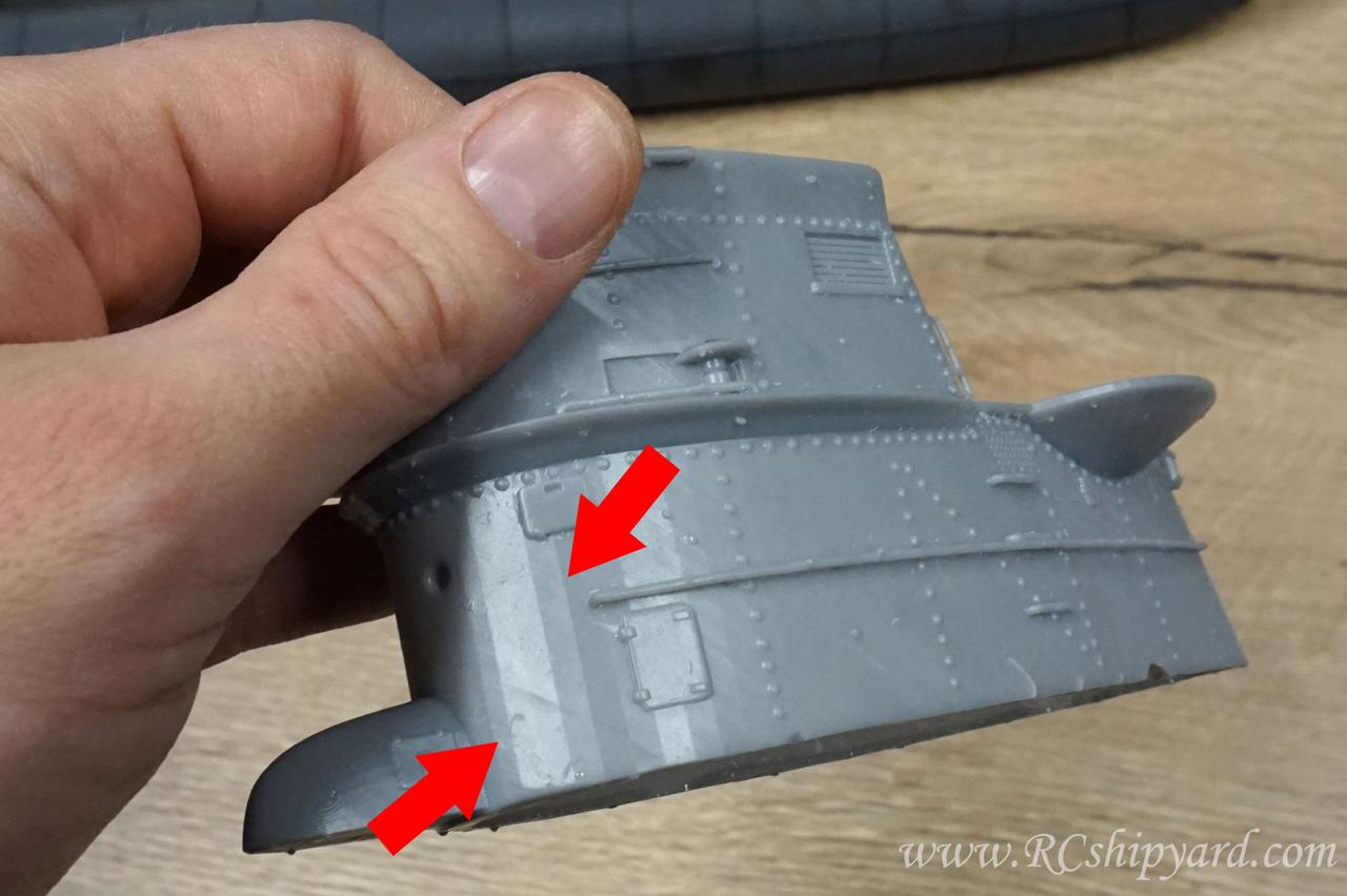
This is no serious damage of course. I actually see this as an opportunity to fix some of the mistakes an make the model even better!
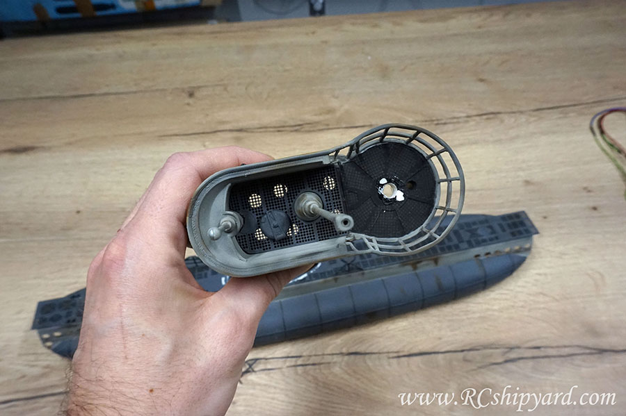
The conning tower of my VIIB which got torn off is very primitive, I designed in a hurry and I based it on some others guys project, sadly copying most of the errors with it. First of all I made the thing to thick…
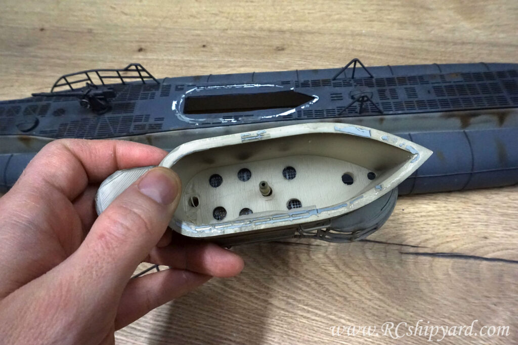 …secondly the amount of venting/flooding holes beneath the floor is not enough. The gaps in the grids/ tower’s floor itself are to small to. A water tension often blocks the air trying to escape. While running on the surface – while turning at higher speeds, it seemed, that the tower is also a little to heavy. So it has to go!

At first I thought about simply getting a ready made file of the internet. I downloaded a nice looking one, but designed for a VIIC… That’s not great, but since it had a large amount of details I thought I’ll try it out. After importing it to the slicing software for a 3d printer I’ve noticed some problems with the floor, it simply shows up partially as solid in the slicing software:
Further inspection and a slicing test run of the model only confirmed my suspicions. The model has serious errors… The floor is there, but partially hidden under some unknown layers of material:
At this time I decided to print the model anyway and check it, the idea was to simply remove the whole floor fabricate a new one and replace it.
After removing the supports and cleaning the model I found something let’s say decent looking, but still requiring lots of work:
The conning tower print still requires modifications, like removing the floor or the bottom layer:
After cutting out the lower layer and removing the floor, I’ve noticed that this thing is thick as stone, even after hollowing the model in the software. So why the hollowing failed? The problem is that this floor is not a single element, but layers of grids apart from themself by ten’s of mm. At this stage I was sure this was not a model intended for printing, but for a render…
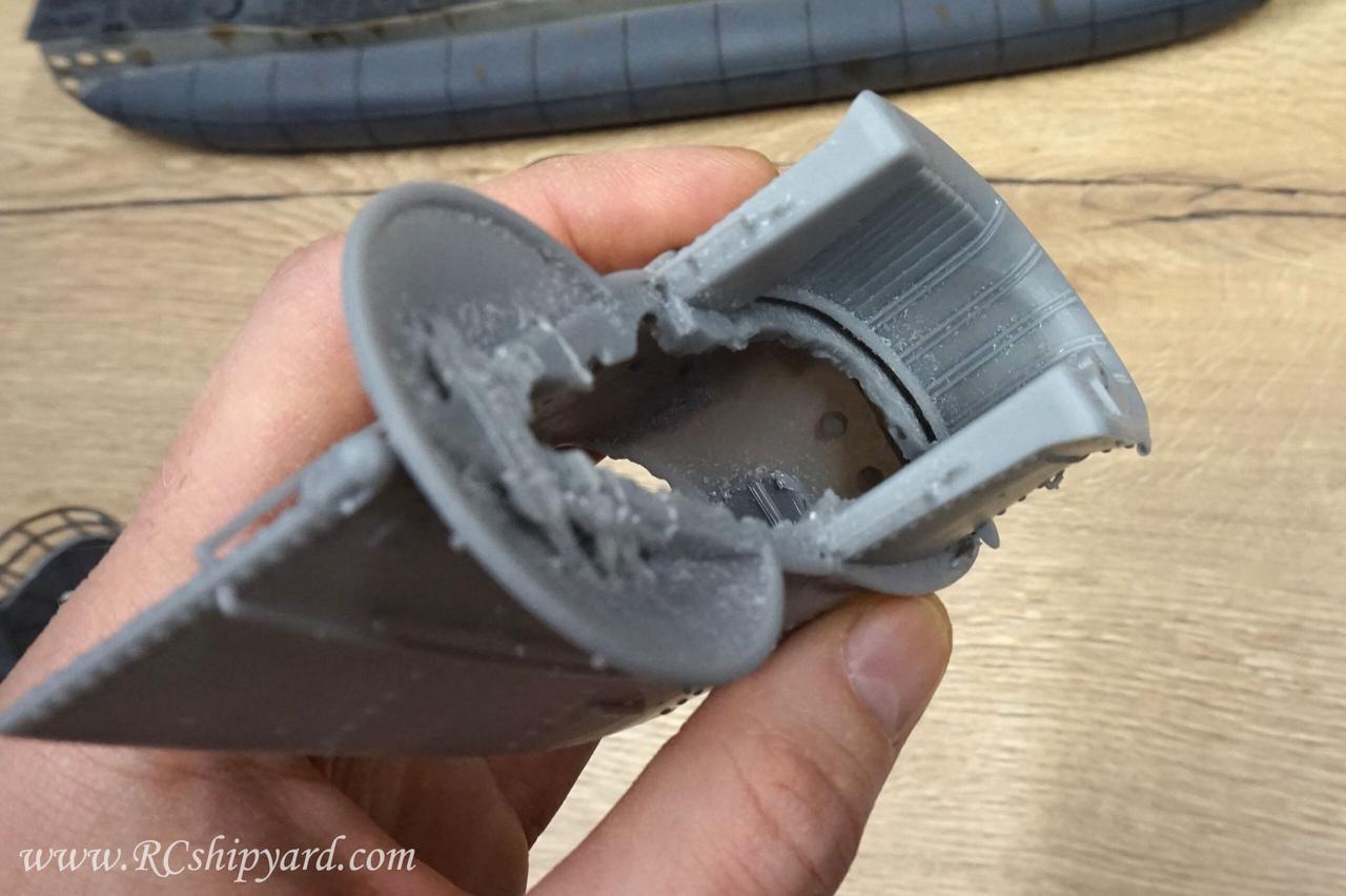
Lastly, after some angular movement under a light I noticed the vertical lines clearly showing that the file was converted to a STL by a person without even basic knowledge about 3d with a serious quality drop, hence the problems. At this time the decision was final about not using this crappy tower.
So, what now?
As always…. I’ll be designing and manufacturing a new element from scratch by my own, with a careful eye for detail this time. This will be a true VIIB conning tower… Here we go!
First the shape, then details. Of course a small preview of the work in progress:
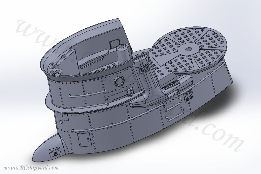
The newly designed model:
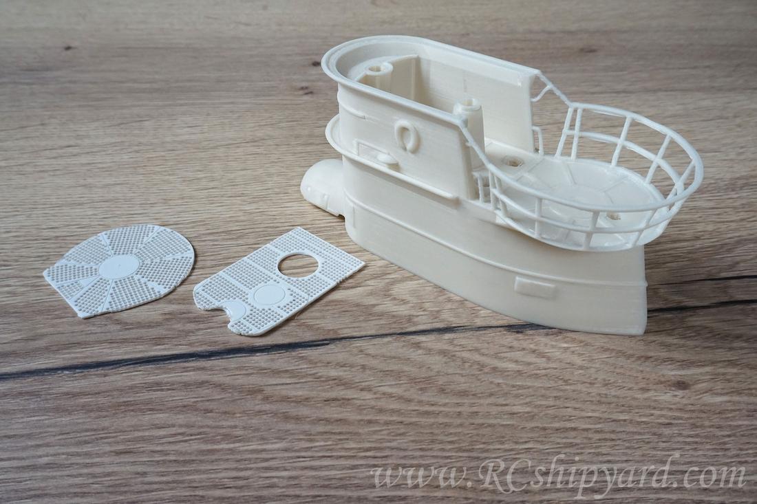
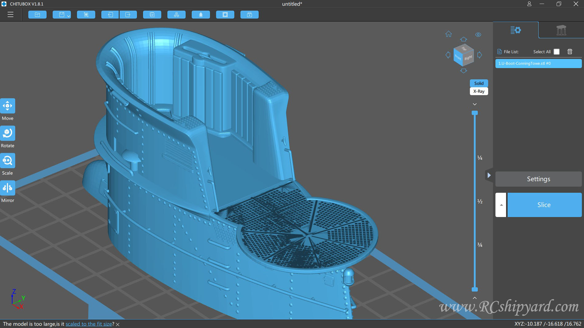
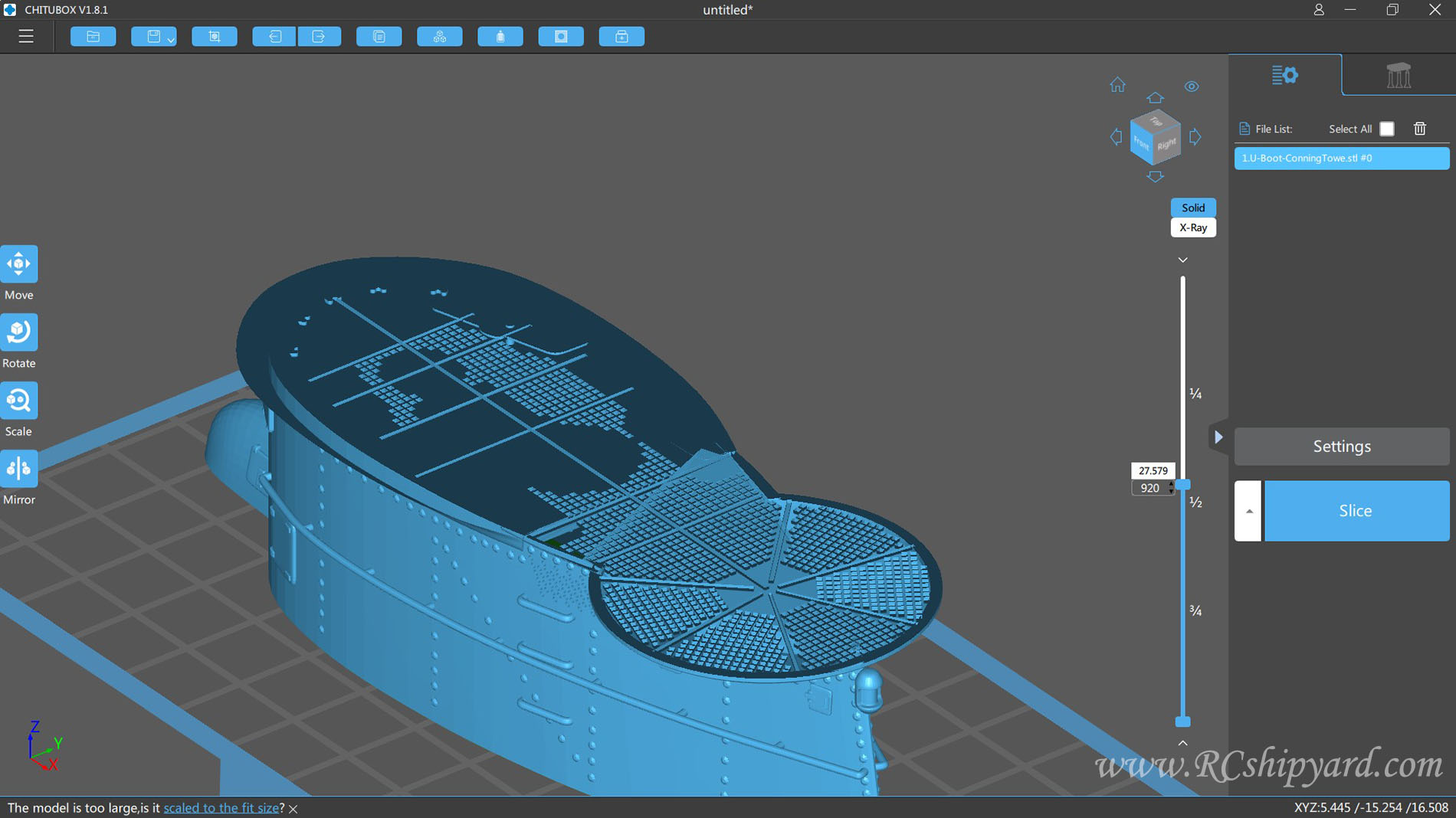
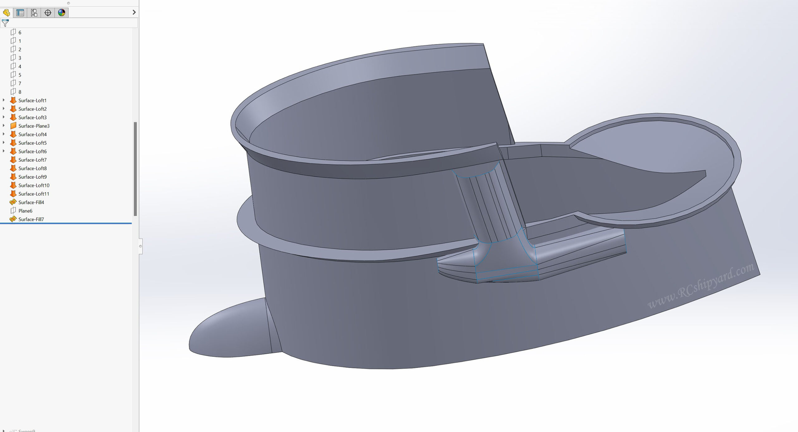
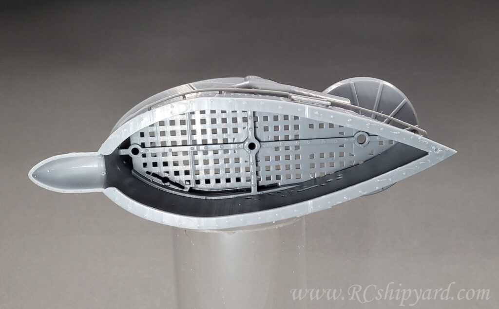
Few days later, I’ve finished designing the new tower. It’s a real VIIB tower, it has been designed using surface modelling with a very thin wall (0.8-1.2mm) to keep the weight and the volume as low as possible. Everything designed for a 4k resin printer.
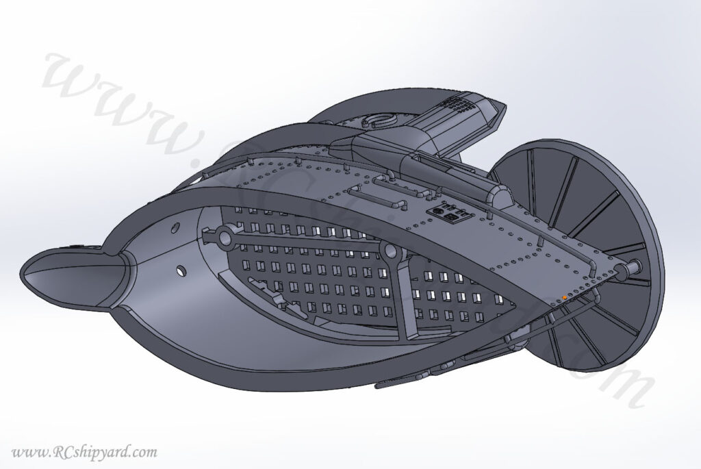
The square shaped grid in the floor is bigger and not to scale on purpose, because I don’t want to have any problems with surface tension and air bubbles getting floor under it. In this model, everything is optimized in such a way to allow an easy flooding/venting of the construction.
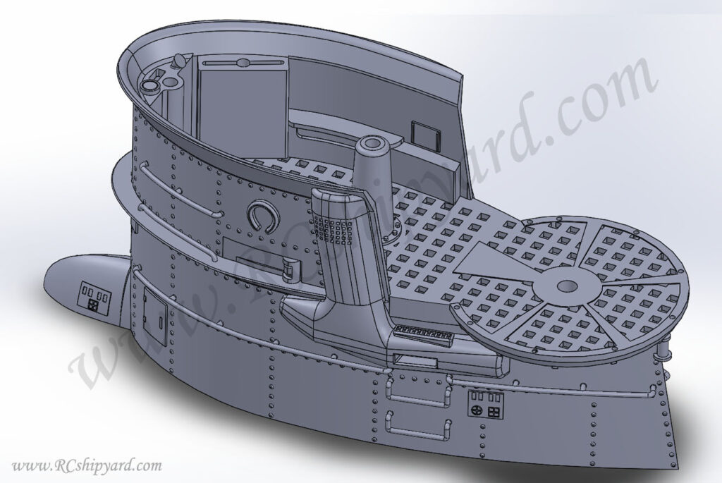
Here You can clearly see as everything is hollowed, additionally in the middle is a cross shaped main support beam. The models lower edge has been designed with a 3mm apron to allow easier gluing in the tower and additionally stiffens the whole construction. Next step will be creating an STL with supports for the resin printer.
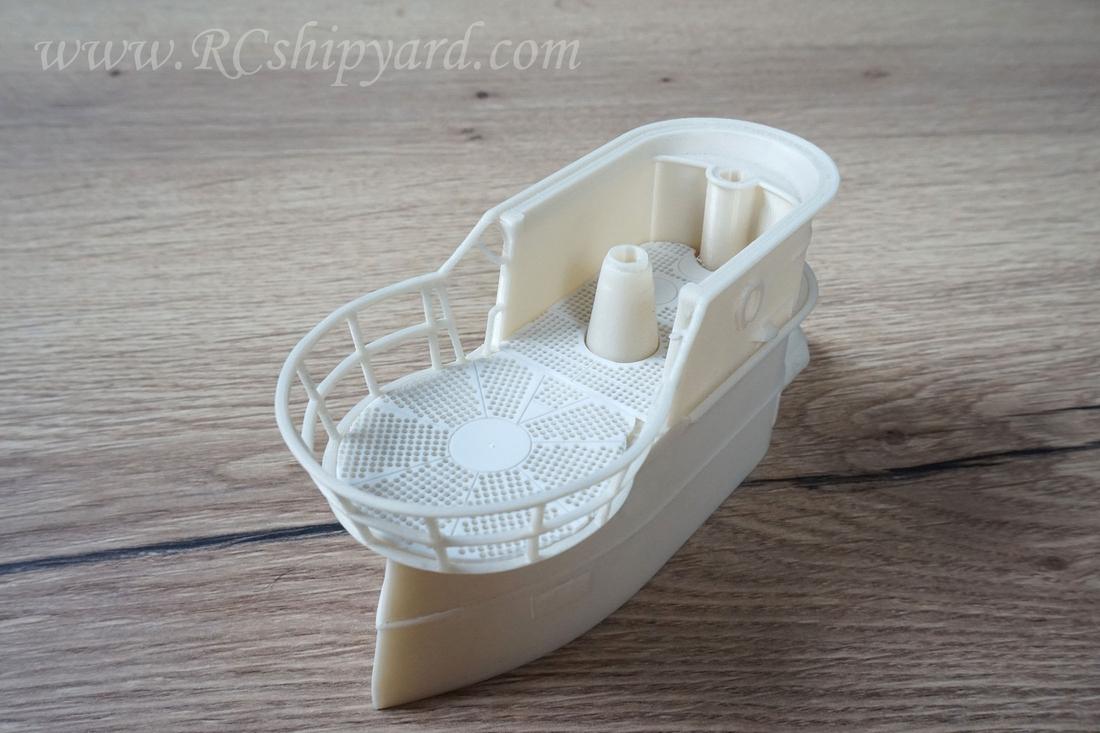
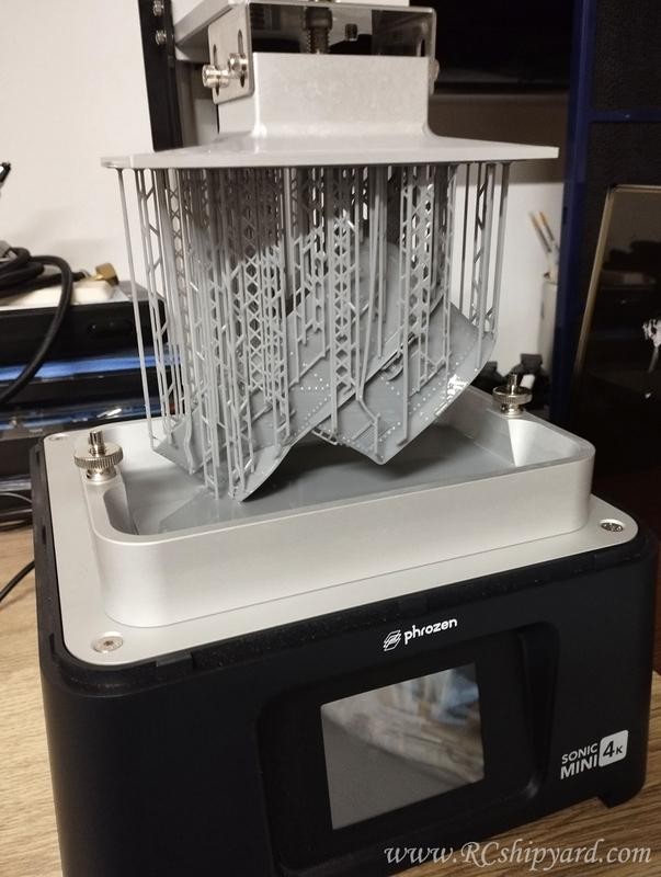
After sometime I found the time to print the project. I did push my printer a little to the limit. As you can see the tip of the model is still in the resin vat, as the project uses the maximum travel height of my printer. Printing time 15 hours + about 2 hours of manual supporting.
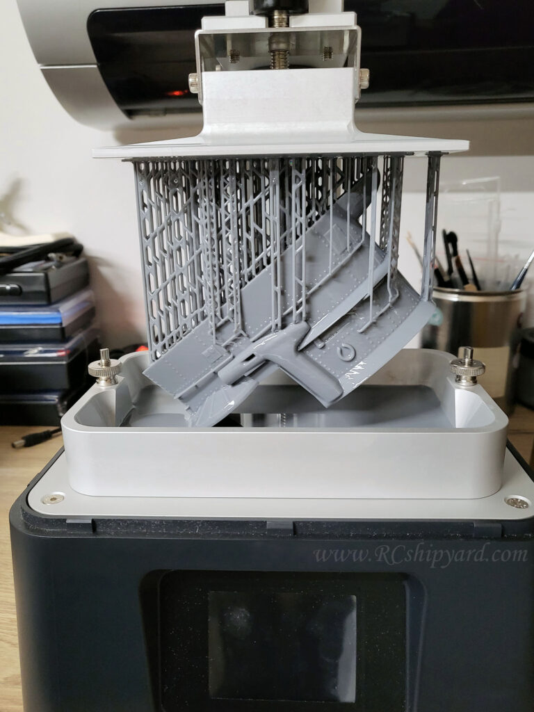
Removing the print from the build plate was actually quite easy yet very messy cause of the model still being wet from left over and uncured resin, the real challenge came a bit later after the cleaning processes…
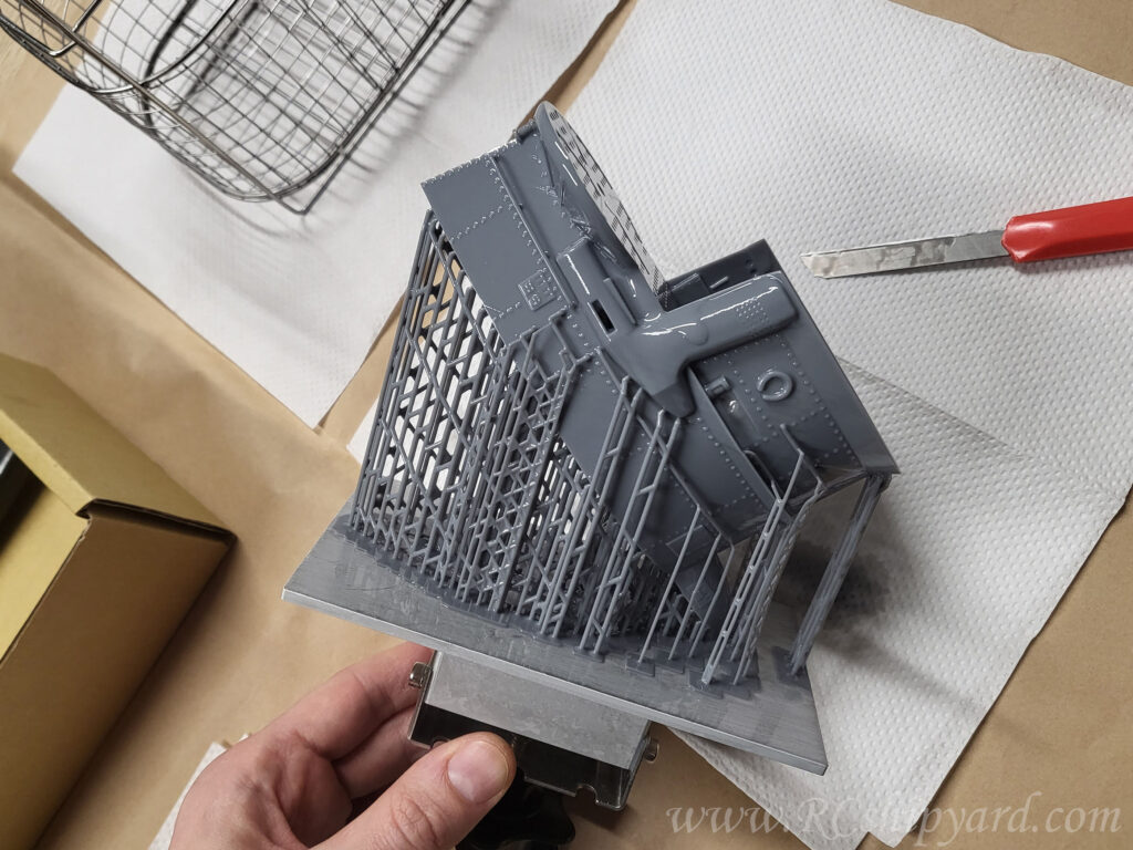
…and this was removing all the support material. This took time and had to be done very carefully as at this stage the print is not fully cured yet.
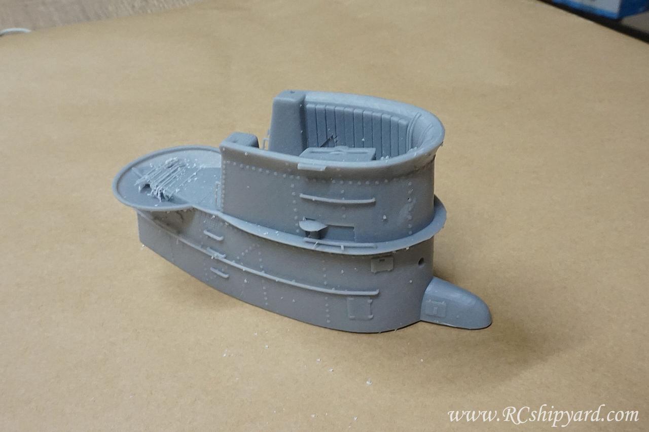
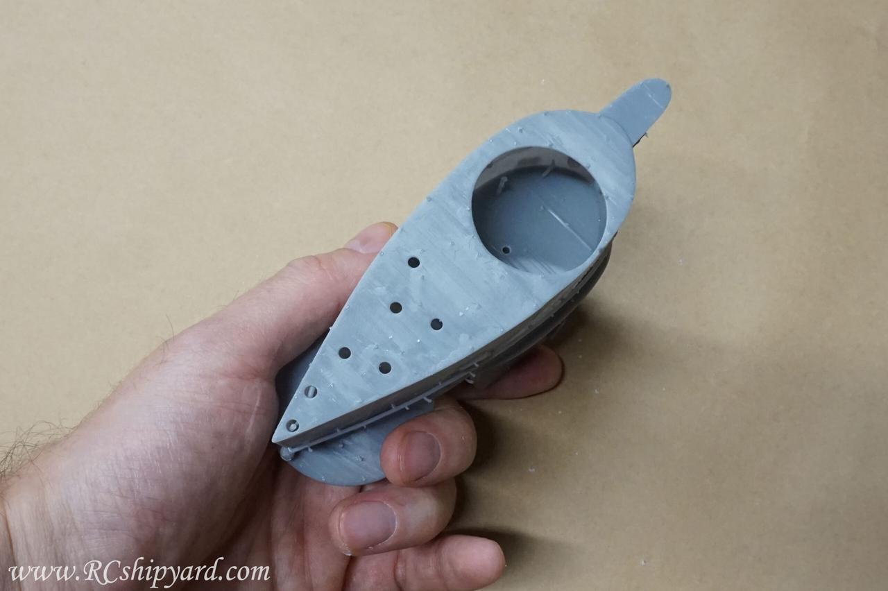
But I must say, that I’m quite happy with the result:
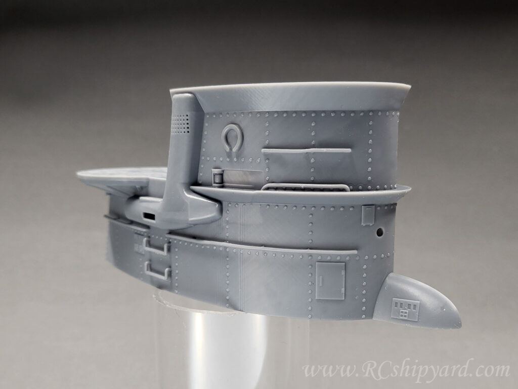
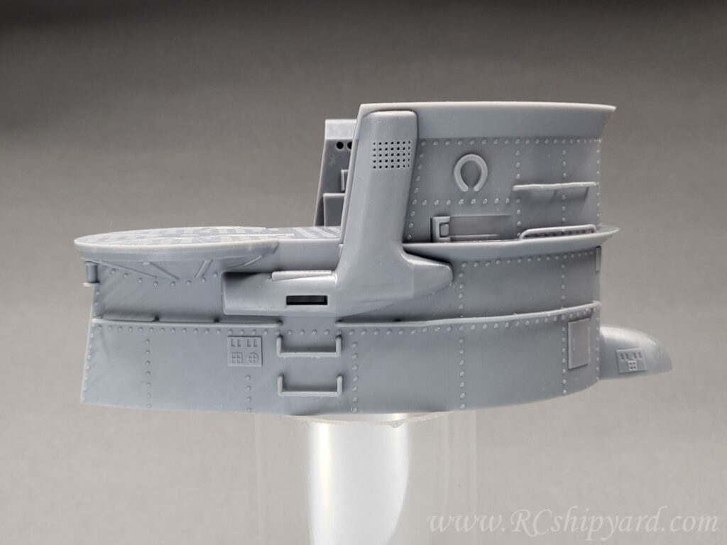
The grid has been designed as slightly bigger than the original one, as in this scale keeping the scaled floor would cause problems with water tension. Bigger grid allows for better venting and flooding – I don’t want to have any air trapped inside cause of the water tension.
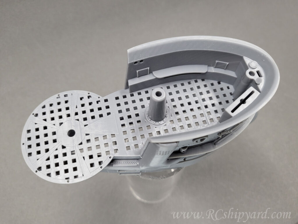
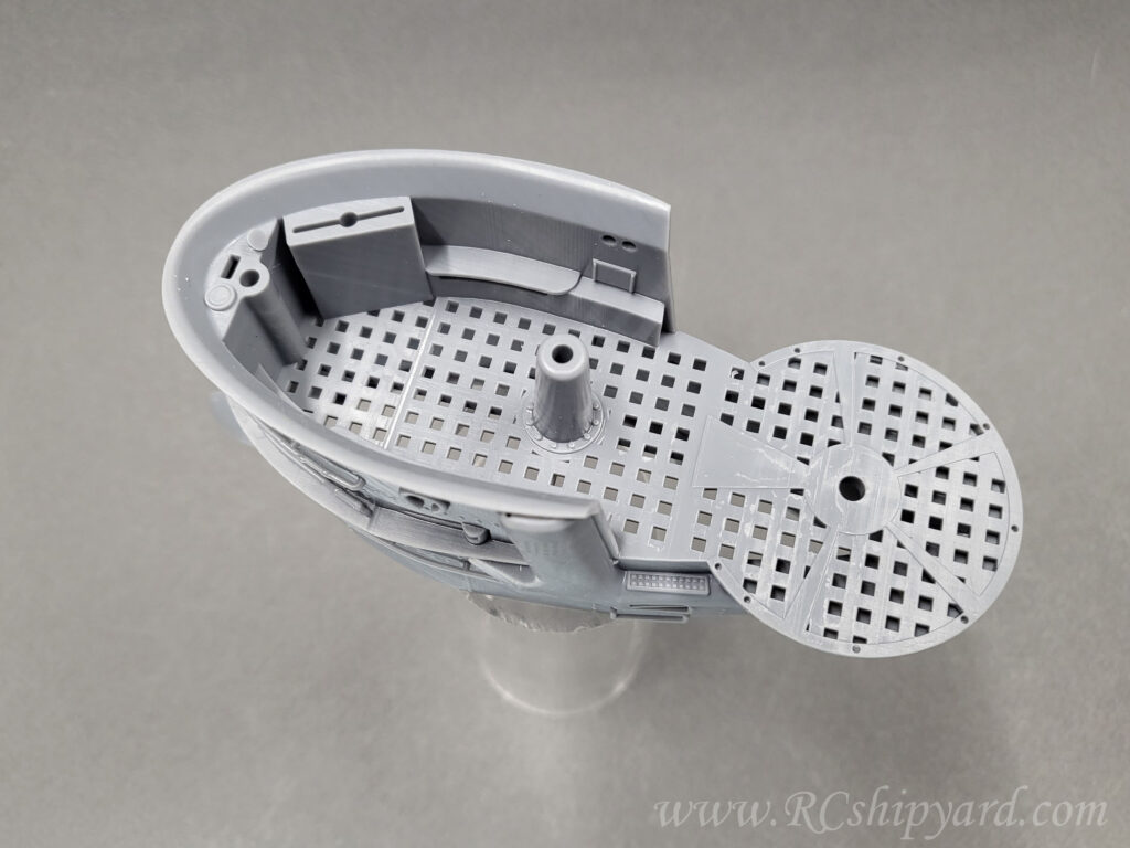
Of course as mentioned earlier at the 3d design stage, the print is hollow and you can see how the structural design looks inside. The model was designed to have as little volume and weight as possible. Every shape, except the structural supports (like the cross here) is hollow with a wall between 0.8 to 1.2mm. This thing is light as a feather.
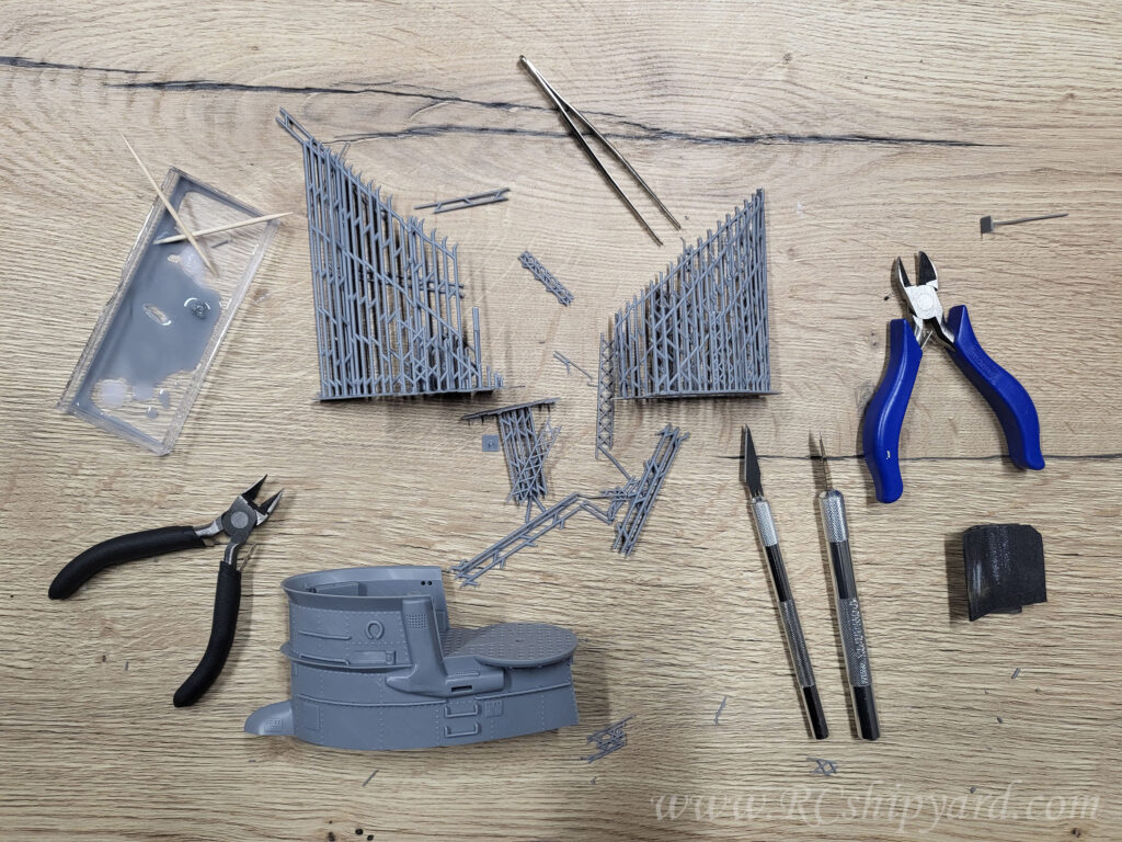
New Details:
I wanted to have new details like the Flak and the deck gun. I was of course still missing the railing for the tower itself too. I decided that I’ll try to push the limits of my printer again, yet this time I’ll check how small details I can make. It a true resolution torture test:
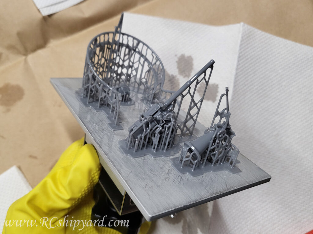
The first one to clean and remove the supports was the deck gun.
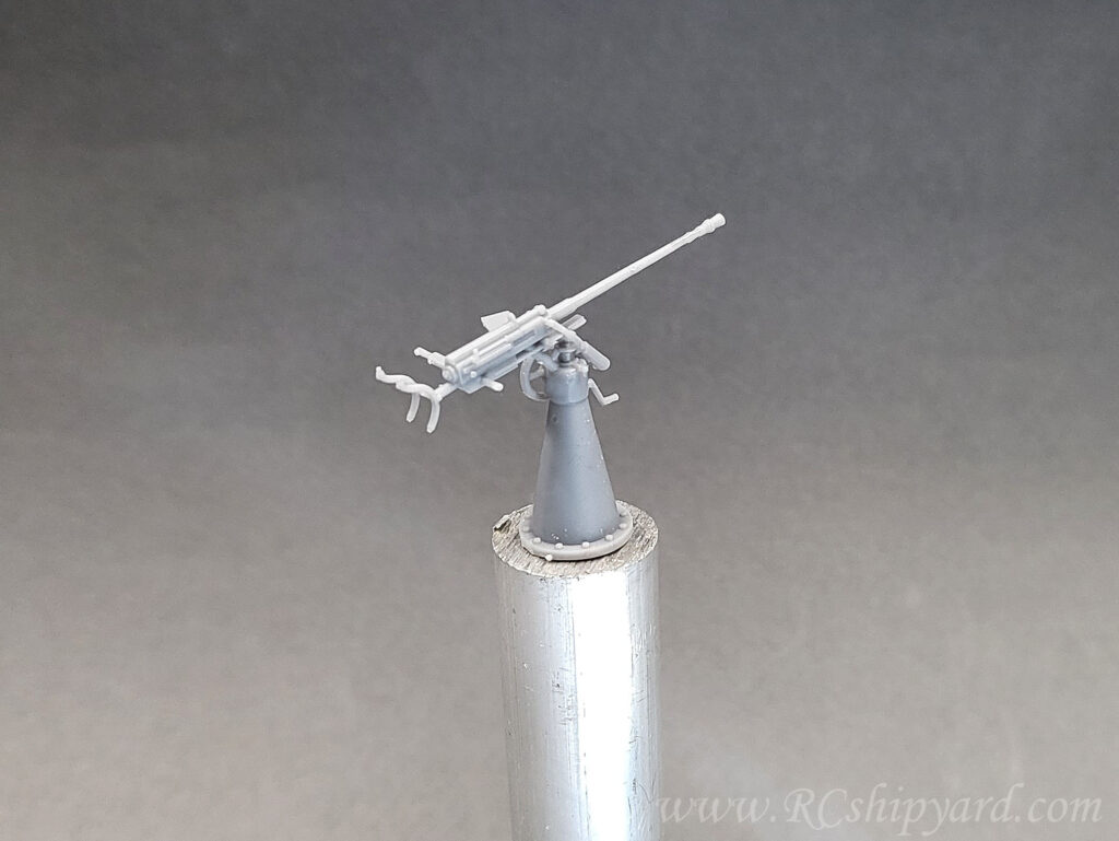
And of course the new deck gun:
This one however still requires some tweaking in the slicer program, as I did lost some of the details cause wrongly placed supports.
The new railing for the tower. Very easy to design and surprisingly easy to clean and remove the supports:
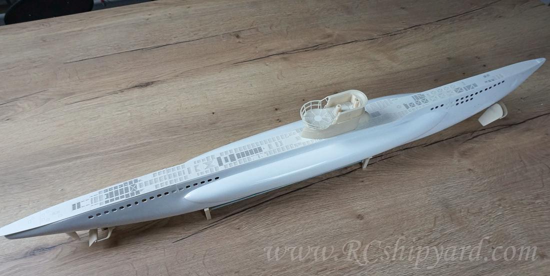
Fitting everything for the first time. The final fit and gluing everything together will be at a much later stage – after the painting of course.
More Soon!
Last update 26.04.2023
Thank you for reading